Rotation angle detecting device

a detection device and rotating angle technology, applied in the field of rotating angle detection devices, can solve the problems of inaccurate output signal of magnetic sensors, difficult to accurately position the sensor elements around the permanent magnet rotor, and difficulty in reducing the size of the rotating angle detection device, so as to achieve accurate and compact rotation angle detection

Inactive Publication Date: 2010-02-16
DENSO CORP +1
View PDF7 Cites 14 Cited by
  • Summary
  • Abstract
  • Description
  • Claims
  • Application Information

AI Technical Summary

Benefits of technology

[0010]Therefore, an object of the invention is to provide a compact and accurate rotation angle detecting device.
[0012]Therefore, a compact rotation angle detecting device can be provided. Further, temperature difference between the pair of sensor elements can be minimized.
[0020]According to another feature of the invention, a pair of magnetic sensor elements is integrally formed on a single chip. Therefore, the angle between the sensor surfaces of the sensor elements can be accurately set to 90 degrees in angle.

Problems solved by technology

Such a rotation angle detecting device has a difficulty in reducing its size because the pair of sensor elements is disposed distant from each other along the circumference of a permanent magnet rotor.
Further, it is difficult to accurately position the sensor elements around the permanent magnet rotor because of vibration when the rotation angle detecting device is installed into a motor vehicle or the like.
Further, because such a sensor element changes its output signal as the temperature surrounding the sensor changes, the magnetic sensor may provide an inaccurate output signal if the temperature surrounding one of the sensor elements is different from the temperature surrounding the other sensor element.
Therefore, it is difficult to accurately convert the output signals to trigonometric functions.

Method used


Image

  • Rotation angle detecting device
  • Rotation angle detecting device
  • Rotation angle detecting device

Examples


first embodiment

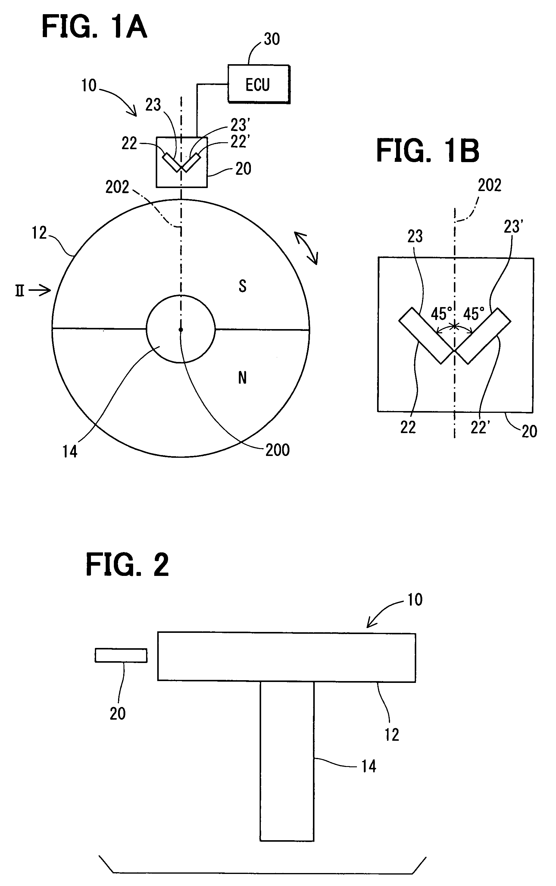
[0056]A rotation angle detecting device 10 according to the invention will be described with reference to FIGS. 1-8.

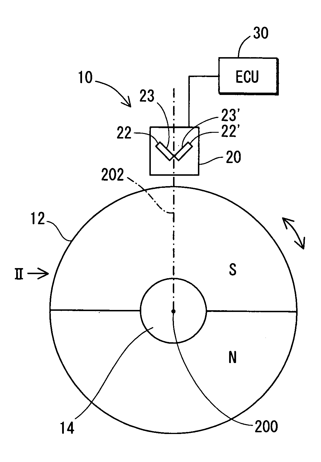
[0057]The rotation angle detecting device 10 is connected to a rotating object, such as an engine crank shaft or a steering wheel of a vehicle in order to detect the rotation angle of the crankshaft or the steering wheel. The rotation angle detecting device 10 includes a disk-shaped permanent magnet rotor 12, a magnetic sensor (hereinafter referred to as the Hall IC) 20, and an electronic control unit (hereinafter referred to as ECU) 30. The permanent magnet rotor 12 is constructed of a pair of semicircular permanent magnets and a rotary shaft 14 that rotates about its rotation axis 200. The permanent magnet rotor 12 is magnetized in a radial direction, as shown in FIG. 18.

[0058]The Hall IC 20 is disposed at a place around the circumference of the permanent magnet rotor 12. The Hall IC 20 includes a pair of Hall elements 22, 22′ and the ECU 30 so as to provide the ECU ...

second embodiment

[0096]A rotation angle detecting device according to the invention is shown in FIGS. 9A and 9B.

[0097]The rotation angle detecting device 40 includes a pair of Hall elements 22, 22′. Each of the Hall elements 22, 22′ has a magnetic sensor surface 23 or 23′ and is arranged to be on an imaginary plane that is perpendicular to the rotation axis 200 of the permanent magnet rotor 12 so that each of the magnetic sensor surfaces 23, 23′ inclines by 45 degrees in angle toward a normal line 202 that intersects the rotation axis 200 at right angles and so that the magnetic sensor surfaces 23 of the pair of magnetic sensor elements 22 are positioned to have 90 degrees in angle between them. Therefore, the Hall elements 23 are disposed symmetric with respect to the line 202.

[0098]However, the sensor surfaces 23, 23′ are arranged to face the permanent magnet rotor 12, which is opposite to the sensor surfaces of the first embodiment.

[0099]A rotation angle detecting device according to the third em...

fourth embodiment

[0101]A rotation angle detecting device 60 according to the invention is shown in FIGS. 11A and 11B.

[0102]Each of the Hall elements 22, 22′ is disposed in the same manner as the fourth embodiment except that the sensor surfaces 23, 23′ are arranged to face in the opposite direction.


PUM


Abstract

A rotation angle detecting device includes a magnetic member for providing a magnetic field, a magnetic sensor for sensing a change in the magnetic field when the magnetic member rotates relative to the magnetic sensor about a rotation axis. The magnetic sensor is disposed at a single position and includes a pair of sensor elements. The pair of sensor elements is disposed on an imaginary plane that is perpendicular to the rotation axis so that sensing surfaces of the sensor elements have 90 degrees in angle to each other and so that each of the sensing surfaces inclines by 45 degrees in angle to a line intersecting the rotation axis at right angles.

Description

CROSS REFERENCE TO RELATED APPLICATION[0001]The present application is based on and claims priority from Japanese Patent Application 2006-227680, filed Aug. 24, 2006, the contents of which are incorporated herein by reference.BACKGROUND OF THE INVENTION[0002]1. Field of the Invention[0003]The present invention relates to a rotation angle detecting device for detecting a rotation angle of a rotating object such as a crank shaft of an engine or a wheel of a vehicle.[0004]2. Description of the Related Art[0005]JP-2003-75108-A discloses a rotation angle detecting device. In such a rotation angle detecting device, a change in magnetic field caused by rotation of a permanent magnet rotor is detected by a pair of magnetic sensor elements for providing a pair of output signals. The output signals are converted into trigonometric functions to calculate the rotation angle of the rotating object.[0006]Such a rotation angle detecting device has a difficulty in reducing its size because the pair...

Claims


Application Information

Patent Timeline
Patent Type & Authority Patents(United States)
IPC IPC(8): G01R33/02G01R33/06
CPCG01D5/145
Inventor MATSUMOTO, KOUICHIROUKAWASHIMA, TAKASHISHIMOMURA, OSAMU
Owner DENSO CORP
Why Eureka
Try Eureka