Tube structure for bicycle cable

Inactive Publication Date: 2012-11-22
ASHIMA LTD
View PDF5 Cites 3 Cited by
  • Summary
  • Abstract
  • Description
  • Claims
  • Application Information

AI Technical Summary

Benefits of technology

[0008]The main objective of the present invention is to provide an improved tube structure for bicycle cable.
[0010]Accordingly, the tubular body is connected with a brake seat which is mounted on a bicycle. The bicycle brake cable passes through the channel of the tubular body so that the tubular body is substantially an outer tube relative to the bicycle brake cable. When the tubular body is impacted with an external force, the rigid metallic member provides an enhanced rigidity to the tubular body for preventing a deformation of the tubular body. And the flexible metallic member and the rigid metallic member are alternately arranged so as to allow the tubular body to be bendable and have a sufficient ductility.

Problems solved by technology

However, the hard metallic outer layer which circumferentially encloses the flexible metallic inner layer limits a ductility of the guide tube.
As the brake cable quickly moves along the guide tube, the guide tube is unable to efficiently eliminate the vibration generated by a movement of the brake cable.

Method used


Image

  • Tube structure for bicycle cable
  • Tube structure for bicycle cable
  • Tube structure for bicycle cable

Examples


Embodiment Construction

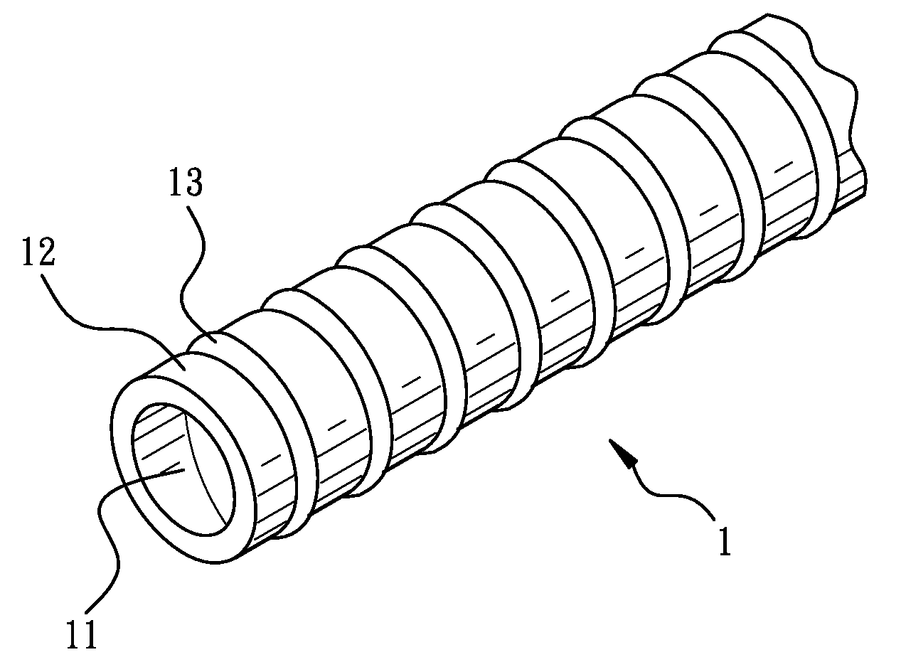
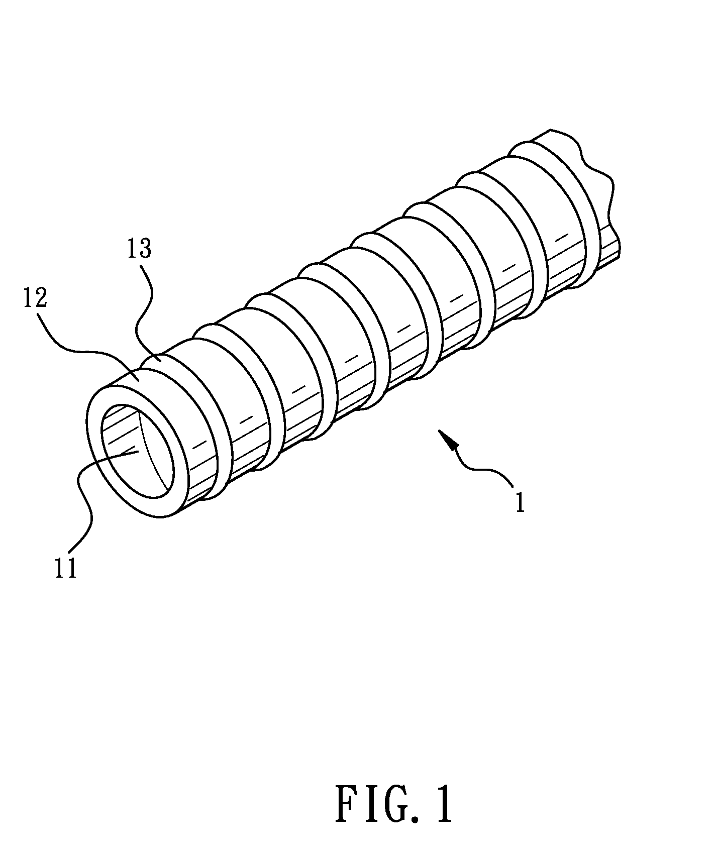
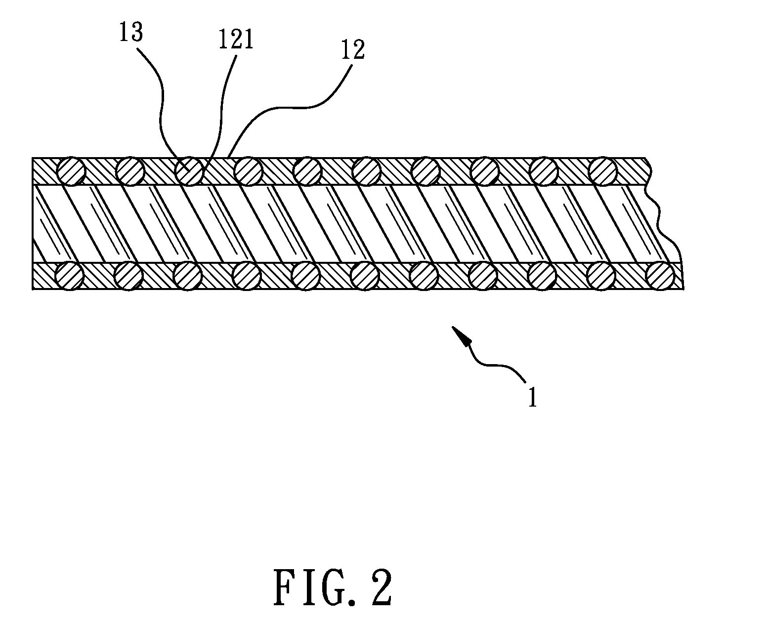
[0016]Referring to the drawings and initially to FIGS. 1-4, a tube structure for bicycle cable in accordance with a preferred embodiment of the present invention comprises a rigid metallic member 12 and a flexible metallic member 13 which is connected with the rigid metallic member 12. The rigid metallic member 12 is an elongated sheet with a predetermined thickness. The rigid metallic member 12 is spirally wound into a tubular body 1. The tubular body 1 has a channel 11 centrally defined therein and axially extending therethrough for adapting to be passed through by a bicycle brake cable 3 (shown in FIG. 4) or a bicycle shifter cable (not shown). The rigid metallic member 12 has two grooves 121 respectively defined in two longitudinal sides thereof. Each groove 121 extends along the corresponding longitudinal side of the rigid metallic member 12 to have a helical arrangement. Each groove 121 has a semi-circular cross section.

[0017]The flexible metallic member 13 is spirally dispose...


PUM


Abstract

A tube structure for bicycle cable includes a rigid metallic member spirally wound into a tubular body. The tubular body has a channel centrally defined therein and axially extending therethrough for adapting to be passed through by a bicycle brake cable. A flexible metallic member is connected with the rigid metallic member and is spirally disposed along a length of the rigid metallic member. When the tubular body is impacted with an external force, the rigid metallic member provides an enhanced rigidity to the tubular body for preventing a deformation of the tubular body. The flexible metallic member and the rigid metallic member are alternately arranged so as to allow the tubular body to be bendable and have a sufficient ductility.

Description

CROSS-REFERENCE TO RELATED APPLICATION[0001]This application is a Continuation-In-Part Application of Ser. No. 13 / 009,858, filed 20 Jan. 2011, and entitled “TUBE STRUCTURE FOR BICYCLE CABLE”, now pending.BACKGROUND OF THE INVENTION[0002]1. Field of the Invention[0003]The present invention relates to a tube structure for bicycle cable, and more particularly to a tube structure formed by spirally winding a rigid metallic member and a flexible metallic member for providing a flexible and ductile effect.[0004]2. Description of Related Art[0005]A conventional guide tube for bicycle brake cable in accordance with the prior art comprises a guide tube. A brake cable passes through the guide tube. The guide tube is formed by a flexible metallic inner layer and a hard metallic outer layer. The guide tube is able to be bent at a predetermined bending angle due to a flexibility provided by the inner layer. The hard metallic outer layer provides a hardness to strengthen the structure of the guid...

Claims


Application Information

Patent Timeline
IPC IPC(8): F16M13/00
CPCB60T11/046F16C1/26B21F45/06
Inventor MOORE, WAYNE-IAN
Owner ASHIMA LTD
Why Eureka
Try Eureka