Heat exchanger

a heat exchanger and heat exchange technology, applied in the field of heat exchangers, can solve the problems of reducing the heat exchange efficiency of conventional heat exchangers, unable to meet current commercial demands, and relatively low heat exchange efficiency of heat exchangers using gas to disperse hea

Inactive Publication Date: 2012-11-22
NATIONAL YUNLIN UNIVERSITY OF SCIENCE AND TECHNOLOGY
View PDF3 Cites 20 Cited by
  • Summary
  • Abstract
  • Description
  • Claims
  • Application Information

AI Technical Summary

Problems solved by technology

A conventional heat exchanger using gas to dissipate heat has a relatively low heat exchange efficiency and cannot meet current commercial demands.
In other words, the flow distribution among the heat exchange tubes 23 is uneven, thereby reducing the heat exchange efficiency of the conventional heat exchanger.
However, such an arrangement may result in an increase in the length of the inlet header tube 21, which makes the heat exchanger inapplicable for a small scale device.

Method used


Image

  • Heat exchanger
  • Heat exchanger
  • Heat exchanger

Examples


examples 1 to 7

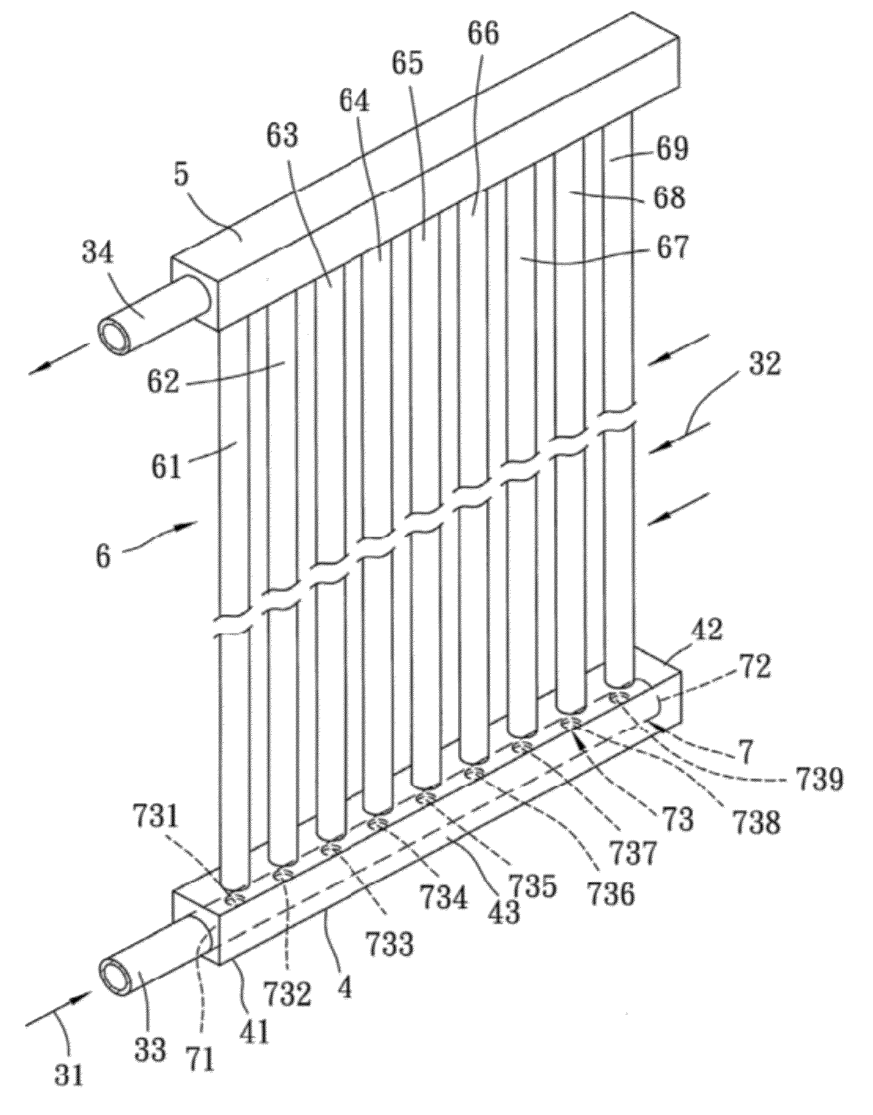
[0038]The heat exchanger of the present invention used in Examples 1 to 7 has a U-type structure as shown in FIG. 5, in which the inlet and outlet header tubes 4, 5 respectively have a square cross section with a width of 9 mm, each of the heat exchange tubes 6 has a circular cross section with an inner diameter of 3 mm, the baffle tube 7 has a circular cross section with an outer diameter of 6 mm and an inner diameter of 4 mm, and each of the orifices 73 of the baffle tube 7 has a circular shape. A distance of the connecting end 60 of the first heat exchange tube 61 from the first end 41 of the inlet header tube A is 3.5 mm, a center-to-center distance between two adjacent orifices 73 is 10 mm, and a center-to-center distance between two adjacent heat exchange tubes 6 is 10 mm. It should be noted that the inflow tube 31 has the same cross section as that of the baffle tube 7 in Examples 1 to 7. The first fluid 31 is water having a temperature of 25° C.

[0039]In Examples 1 to 7, each...


PUM


Abstract

A heat exchanger includes: an inlet header tube including opposite first and second ends and an inner space formed between the first and second ends; an outlet header tube parallel to the inlet header tube; a plurality of heat exchange tubes transversely extending between and fluidly connected to the inlet and outlet header tubes, each of the heat exchange tubes having a connecting end connected to the inlet header tube; and a baffle tube inserted into the inner space of the inlet header tube. The baffle tube has an open end proximate to the first end, a closed end proximate to the second end, and a plurality of orifices disposed between the open and closed ends to fluidly intercommunicate the inner space of the inlet header tube and the baffle tube. Each of the orifices is disposed in alignment with the connecting end of one of the heat exchange tubes.

Description

BACKGROUND OF THE INVENTION[0001]1. Field of the Invention[0002]This invention relates to a heat exchanger, more particularly to a heat exchanger that includes a baffle tube inserted in an inlet header tube.[0003]2. Description of the Related Art[0004]Heat exchangers are widely applied to various devices such as condensers, evaporators, boiler furnaces, heat collectors using solar panels, heat radiators of nuclear reactors or electronic equipments, etc. The heat transfer efficiency of a heat exchanger is generally improved by an increase in the heat transfer area of the heat exchanger.[0005]A conventional heat exchanger using gas to dissipate heat has a relatively low heat exchange efficiency and cannot meet current commercial demands. Therefore, it is desired in the art to increase the heat exchange efficiency of a heat exchanger by utilizing liquid to dissipate heat.[0006]FIGS. 1 and 2 show a conventional heat exchanger that is usually used in an electronic equipment or a solar en...

Claims


Application Information

Patent Timeline
Patent Type & Authority Applications(United States)
IPC IPC(8): F28F9/02
CPCF24J2/245F24J2/4647Y02E10/44F28D1/05316F28F9/0273F24S80/30F24S10/742
Inventor CHEN, ING-YOUNTSAI, JHONG-SYUANWANG, CHI-CHUAN
Owner NATIONAL YUNLIN UNIVERSITY OF SCIENCE AND TECHNOLOGY
Why Eureka
Try Eureka