Magnetic member
- Summary
- Abstract
- Description
- Claims
- Application Information
AI Technical Summary
Benefits of technology
Problems solved by technology
Method used
Image
Examples
first embodiment
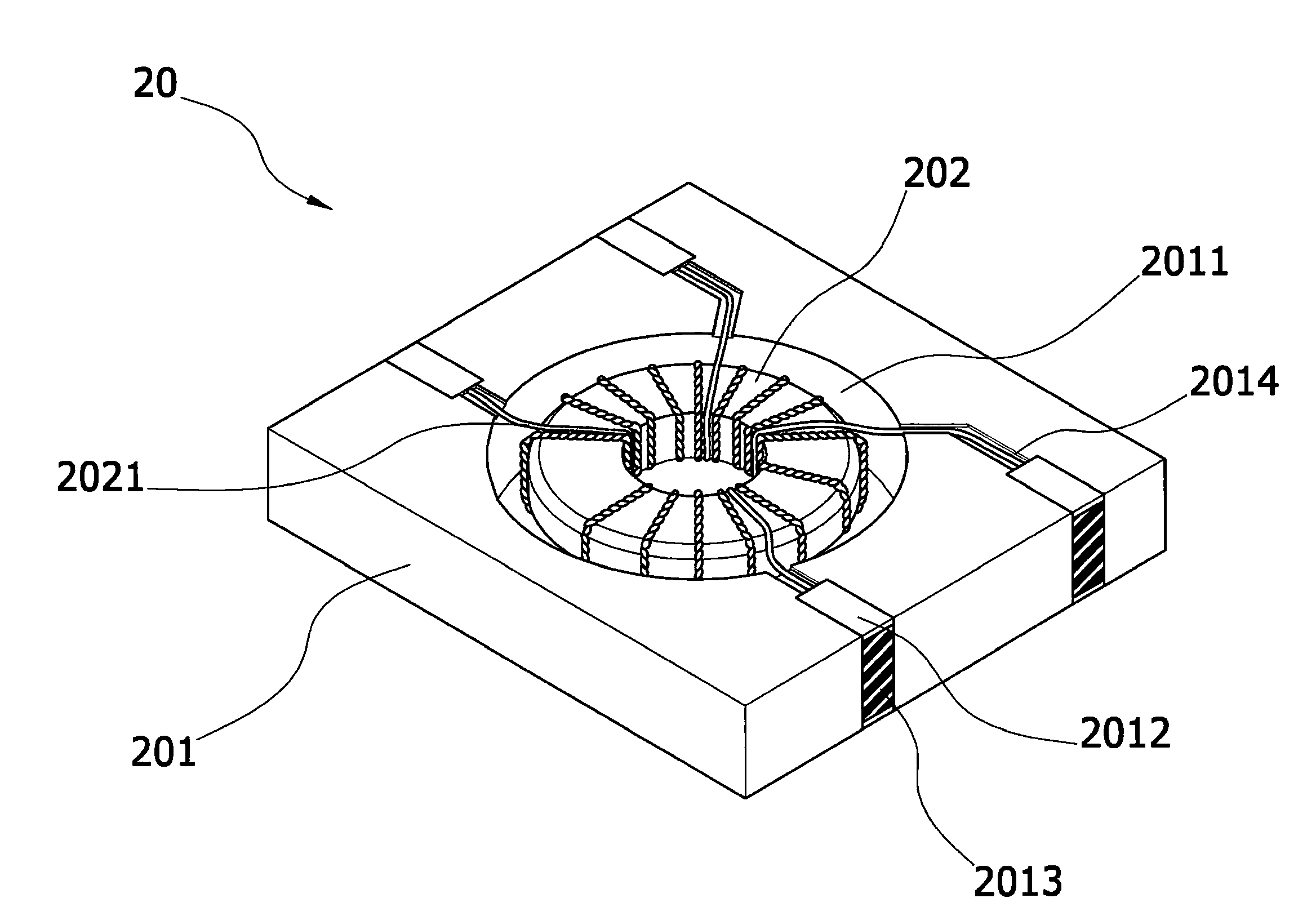
[0019]FIG. 6 is a schematic implementation view of the present invention. Referring to FIG. 6, during an IR reflow process of the magnetic member 20, tin liquid 21 may be attached to a surface edge of the guide groove 2013 to form a preferred “tin climbing phenomenon” (as shown by A in the figure), so that the magnetic member 20 may be steadily adhered to a circuit board 22, and as the tin liquid 21 has a large contact area with the guide groove 2013, the circuit board 22 generates good conductivity with the magnetic member 20. FIG. 7 is the present invention. Referring to FIG. 7, a first electrode 2012 may be formed on the substrate 201, and a second electrode 2016 may be further formed on another plane opposite to the first electrode 2012. The guide groove 2013 is formed between two conductive terminals (2012 and 2016), so that the two conductive terminals (2012 and 2016) are electrically connected. Accordingly, after the magnetic member 20 completes the configuration, the formed ...
second embodiment
[0020]FIG. 8 is the present invention. Referring to FIG. 8, in the magnetic member 20, a cover plate 203 is further configured on an upper edge of the substrate 201, so that the carried relevant elements and the formed circuits on the magnetic member 20 may be protected by the cover plate 203, in which the cover plate 203 may be a ceramic substrate. Furthermore, an electrical line 2031 may be formed on a surface edge of the cover plate 203, and the electrical line 2031 may be electrically connected to the magnetic member 20 to form a magnetic member of a circuit board type after the integral manufacturing. Furthermore, in the above embodiment, as an example, a cover plate 203 is additionally disposed on the upper edge of the substrate 201, but the present invention is not limited thereto. The cover plate 203 may be additionally disposed on a lower edge of the substrate 201, or a cover plate 203 is respectively additionally disposed on the upper edge and the lower edge of the substra...
third embodiment
[0021]FIG. 9 is the present invention. Referring to FIG. 9, the configuration groove 2011 on the substrate 201 may be in a perforated form. According to this embodiment, during assembly, the magnetic element 202 is temporarily limited by a jig (not shown), and after the magnetic element 202 completes the configuration and the filling of the adhesive layer 2015 is completed, the jig is removed.
PUM
 Abstract
Description
Claims
Application Information
 - R&D
- Intellectual Property
- Life Sciences
- Materials
- Tech Scout
- Unparalleled Data Quality
- Higher Quality Content
- 60% Fewer Hallucinations
Browse by: Latest US Patents, China's latest patents, Technical Efficacy Thesaurus, Application Domain, Technology Topic, Popular Technical Reports.
© 2025 PatSnap. All rights reserved.Legal|Privacy policy|Modern Slavery Act Transparency Statement|Sitemap|About US| Contact US: help@patsnap.com


