
Magnetic member

a technology of magnetic members and insulating plates, applied in the field of magnetic members, can solve the problems of easy generation of poor conductivity, avoid adhesion conditions and poor conduction conditions, and increase the conduction area

Inactive Publication Date: 2014-02-25
MAG LAYERS SCI TECHNICS
View PDF2 Cites 2 Cited by
  • Summary
  • Abstract
  • Description
  • Claims
  • Application Information

AI Technical Summary

Benefits of technology

The present invention is about a magnetic member that can avoid adhesion and conduction issues after an IR reflow process. It includes a substrate and a magnetic element. The substrate has a groove to accommodate the magnetic element and a first electrode on its surface. The guide groove on the substrate edge is filled with conductive material to connect the first electrode to it. This design ensures stable adhesion of the magnetic element to the circuit board and avoids poor conduction condition after reflow process.

Problems solved by technology

Therefore, a condition of poor conductivity is easily generated.

Method used


Image

  • Magnetic member
  • Magnetic member
  • Magnetic member

Examples


first embodiment

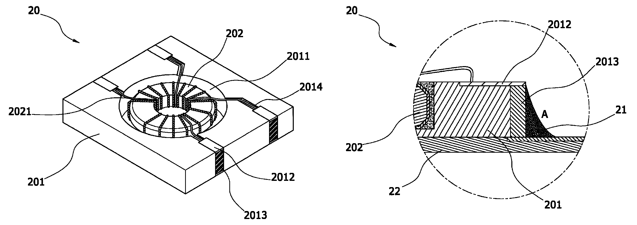
[0019]FIG. 6 is a schematic implementation view of the present invention. Referring to FIG. 6, during an IR reflow process of the magnetic member 20, tin liquid 21 may be attached to a surface edge of the guide groove 2013 to form a preferred “tin climbing phenomenon” (as shown by A in the figure), so that the magnetic member 20 may be steadily adhered to a circuit board 22, and as the tin liquid 21 has a large contact area with the guide groove 2013, the circuit board 22 generates good conductivity with the magnetic member 20. FIG. 7 is the present invention. Referring to FIG. 7, a first electrode 2012 may be formed on the substrate 201, and a second electrode 2016 may be further formed on another plane opposite to the first electrode 2012. The guide groove 2013 is formed between two conductive terminals (2012 and 2016), so that the two conductive terminals (2012 and 2016) are electrically connected. Accordingly, after the magnetic member 20 completes the configuration, the formed ...

second embodiment

[0020]FIG. 8 is the present invention. Referring to FIG. 8, in the magnetic member 20, a cover plate 203 is further configured on an upper edge of the substrate 201, so that the carried relevant elements and the formed circuits on the magnetic member 20 may be protected by the cover plate 203, in which the cover plate 203 may be a ceramic substrate. Furthermore, an electrical line 2031 may be formed on a surface edge of the cover plate 203, and the electrical line 2031 may be electrically connected to the magnetic member 20 to form a magnetic member of a circuit board type after the integral manufacturing. Furthermore, in the above embodiment, as an example, a cover plate 203 is additionally disposed on the upper edge of the substrate 201, but the present invention is not limited thereto. The cover plate 203 may be additionally disposed on a lower edge of the substrate 201, or a cover plate 203 is respectively additionally disposed on the upper edge and the lower edge of the substra...

third embodiment

[0021]FIG. 9 is the present invention. Referring to FIG. 9, the configuration groove 2011 on the substrate 201 may be in a perforated form. According to this embodiment, during assembly, the magnetic element 202 is temporarily limited by a jig (not shown), and after the magnetic element 202 completes the configuration and the filling of the adhesive layer 2015 is completed, the jig is removed.


PUM

PropertyMeasurementUnit
magneticaaaaaaaaaa
conductiveaaaaaaaaaa
contact areaaaaaaaaaaa

Abstract

A magnetic member includes a substrate and a magnetic element. A configuration groove is formed on the substrate, so as to accommodate the magnetic element. Furthermore, a first electrode is formed on a periphery of the substrate, so that ends of a conductive coil of the magnetic element are electrically laid thereon. A guide groove is formed on a position adjacent to the first electrode, and the guide groove is filled with a conductive metal, so that the first electrode is electrically connected to the guide groove. In this way, after an IR reflow process of the magnetic member, conditions of abnormal adhesion and poor conductivity are avoided. The magnetic member is applicable to various electronic devices requiring the magnetic elements, for example, a communication circuit and a frequency conversion circuit.

Description

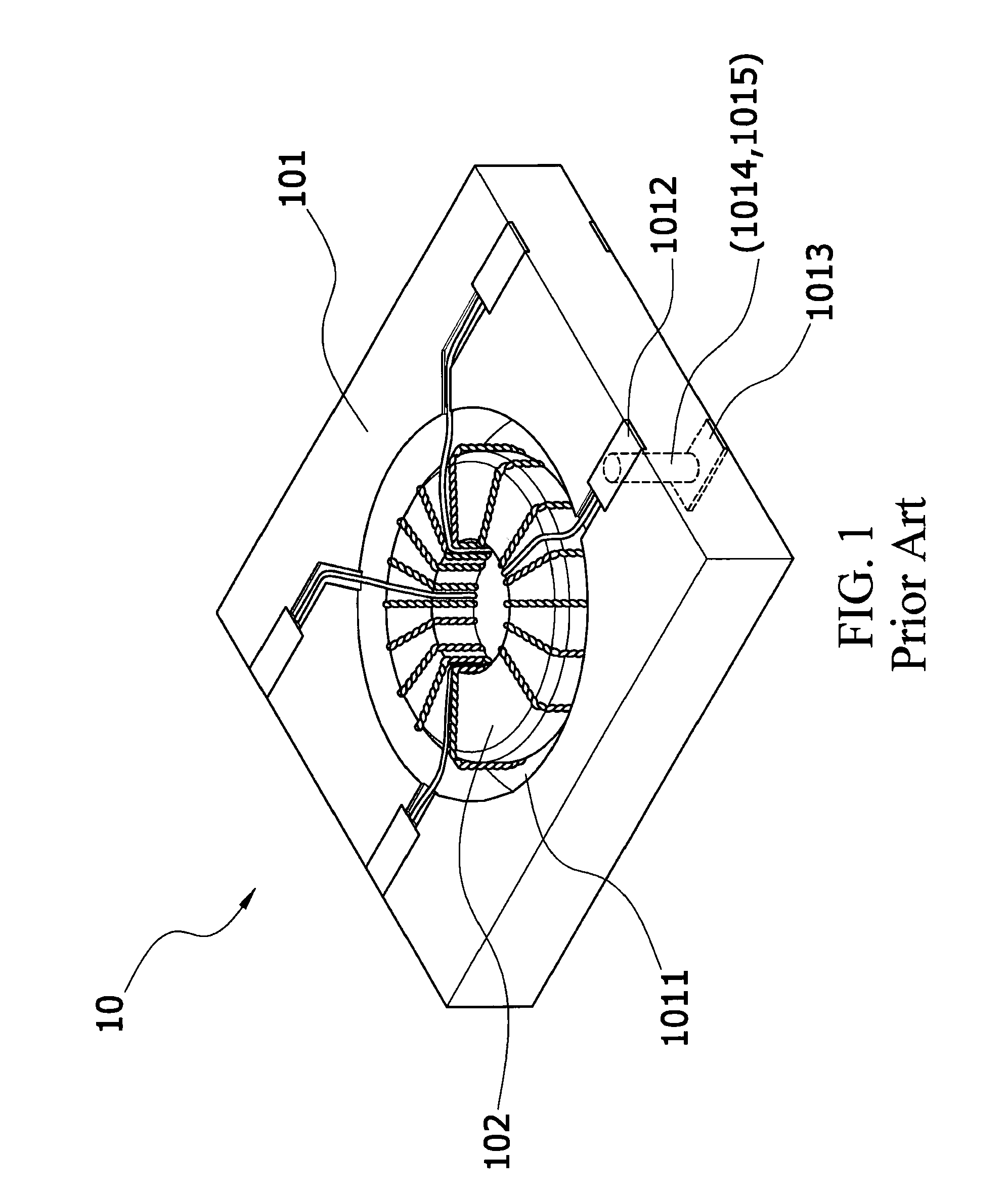
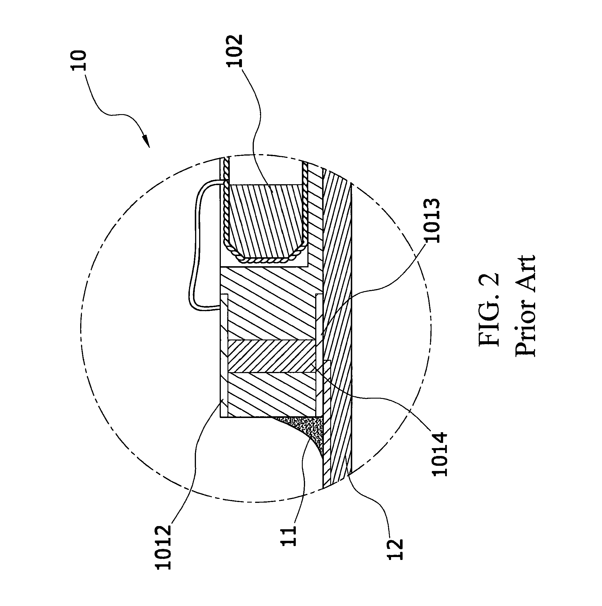
BACKGROUND OF THE INVENTION[0001]1. Field of Invention[0002]The present invention relates to a magnetic member, and more particularly to a magnetic member, in which a penetrated-form guide groove is formed on an edge of a substrate, and the guide groove is electrically connected to a first electrode, so as to avoid an adhesion condition and a poor conduction condition generated after an IR reflow process.[0003]2. Related Art[0004]Currently, any electronic device mainly includes a plurality of active elements and passive elements, and the passive elements match active elements to form an electronic control loop having a specific effect. The passive elements are, for example, a magnetic element and a resistor, in which the magnetic element (for example, a transformer or an inductor) has a characteristic that a magnetic field is generated once a current is conducted, and the magnetic element is also one of very important elements of the current electronic device. Take a portable cell p...

Claims


Application Information

Patent Timeline
Patent Type & Authority Patents(United States)
IPC IPC(8): H01F5/00H01F27/28
CPCH01F27/292H01F2027/065
Inventor CHENG, CHING-YUAN
Owner MAG LAYERS SCI TECHNICS
Learn More