Eureka AIR delivers breakthrough ideas for toughest innovation challenges, trusted by R&D personnel around the world.

Electric connector

A technology of electrical connectors and welding parts, which is applied in the direction of connection, circuit, contact parts, etc., can solve the problem that the battery connector cannot meet the needs of customers, and achieve the effect of improving current transmission capacity, reducing height, and reducing contact impedance

Active Publication Date: 2016-11-23
TYCO ELECTRONICS (SHANGHAI) CO LTD
View PDF7 Cites 7 Cited by
  • Summary
  • Abstract
  • Description
  • Claims
  • Application Information

AI Technical Summary

Problems solved by technology

However, the aforementioned several forms of battery connectors in the prior art cannot meet the needs of customers in these several forms.

Method used


Image

  • Electric connector
  • Electric connector
  • Electric connector

Examples


Embodiment Construction

[0039] The technical solutions of the present invention will be further described in detail below through embodiments and in conjunction with the accompanying drawings. In the specification, the same or similar reference numerals refer to the same or similar parts. The following description of the embodiments of the present invention with reference to the accompanying drawings is intended to explain the general inventive concept of the present invention, and should not be construed as a limitation of the present invention.

[0040] Furthermore, in the following detailed description, for convenience of explanation, numerous specific details are set forth in order to provide a thorough understanding of the embodiments of the present disclosure. Obviously, however, one or more embodiments may be practiced without these specific details. In other instances, well-known structures and devices are shown in diagram form in order to simplify the drawings.

[0041] According to a gene...


PUM


Abstract

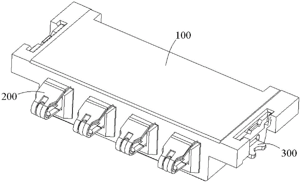
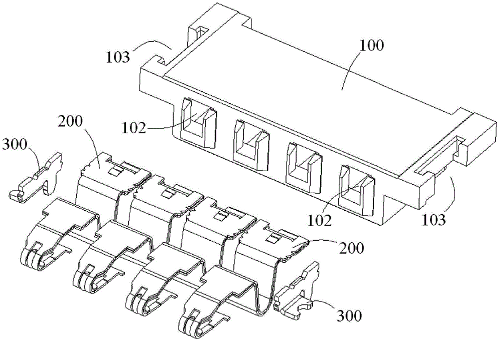
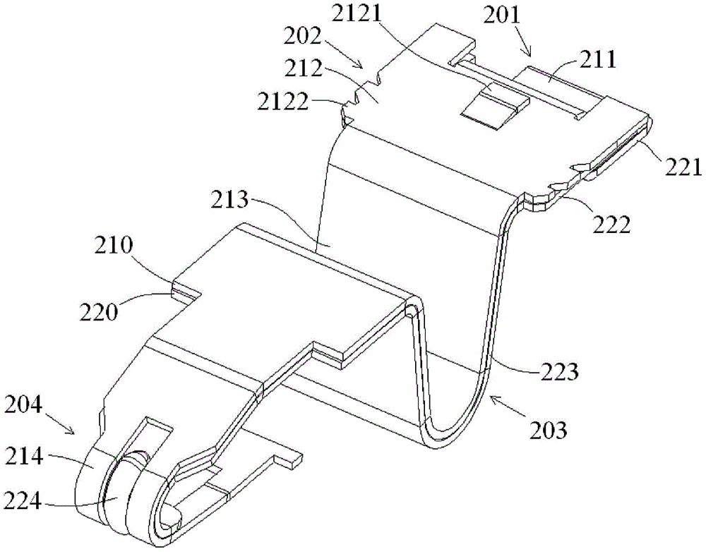
The invention discloses an electric connector comprising an insulating body and multiple terminals. Each of the multiple terminals is provided with a first metal layer and a second metal layer which is arranged on the bottom side of the first metal layer, and the first metal layer is provided with a first electric contact, the second metal layer is provided with a second electric contact and the first electric contact and the second electric contact are arranged in a way of being suitable for simultaneously contacting the corresponding matching terminals. According to the electric connector, each terminal is provided with two metal layers which are vertically laminated so that the conductive area of the whole terminal can be increased, the resistance of the whole terminal can be reduced, the current transmission capacity of the terminal can be enhanced and thus high current can be transmitted. Besides, the two metal layers of each terminal are provided with the electric contacts contacted with the matching terminals of an external circuit so that the two metal layers of each terminal can be electrically contacted with the matching terminals simultaneously, the contact impedance of the terminals can be reduced and the electric contact reliability of the terminals can be enhanced.

Description

technical field [0001] The present invention relates to an electrical connector, in particular to a battery connector. Background technique [0002] A battery connector generally includes an insulating body and a plurality of terminals. A plurality of terminal accommodating grooves are formed in the insulating body, and a plurality of terminals are respectively held in the plurality of terminal accommodating grooves. In the prior art, the terminals of the battery connector mainly include the following forms: pogopin type terminals, leaf type terminals and snake contact type terminals. [0003] The existing battery connectors with pogo pin terminals have disadvantages such as unreliable electrical contact, small current that can be transmitted, the overall height of the electrical connector is too high, and the price is too expensive. The existing battery connectors with blade-shaped terminals have disadvantages such as small current that can be transmitted, and the overall...

Claims


Application Information

Patent Timeline
Patent Type & Authority Applications(China)
IPC IPC(8): H01R13/24H01R12/71H01M2/20
CPCY02E60/10
Inventor 何家勇何文科薛章兰
Owner TYCO ELECTRONICS (SHANGHAI) CO LTD
Why Eureka
Eureka Blog
Learn More