Light emitter with heat-dissipating module

a technology of light emitter and heat dissipation module, which is applied in the direction of semiconductor devices, semiconductor devices for light sources, and semiconductor/solid-state device details. it can solve the problems of reducing heat dissipation efficiency, so as to increase the thermal conductive area and enhance heat dissipation

Inactive Publication Date: 2011-03-15
SUNONWEALTH ELECTRIC MACHINE IND
View PDF9 Cites 7 Cited by
  • Summary
  • Abstract
  • Description
  • Claims
  • Application Information

AI Technical Summary

Benefits of technology

[0008]It is therefore the primary objective of this invention to provide a light emitter with heat-dissipating module that enhance heat dissipation by combining a supporting plate of a light unit with a heat-dissipating member tightly and reliably to increase thermal conductive area.
[0009]The second objective of the present invention is to provide a light emitter with heat-dissipating module that has simplified structure and a small volume resulted from tight and reliable combination of the supporting plate and the heat-dissipating member for miniaturizing and lightening products.

Problems solved by technology

Additionally, the back of each light source may not fully contact with the heat sink.
Thus, heat generated by each of the LED base-plate and LEDs is conducted to the heat sink only through a small contact area between the heat sink and the LED base-plate or LEDs to reduce heat dissipating efficiency.
Besides, using the heat-dissipating fan to draw air to dissipate heat will complicate the structure and enlarge the overall volume of the light emitter.
Therefore, it's difficult to improve the design of the conventional light emitter with heat-dissipating module to achieve miniature and light features.

Method used


Image

  • Light emitter with heat-dissipating module
  • Light emitter with heat-dissipating module
  • Light emitter with heat-dissipating module

Examples


first embodiment

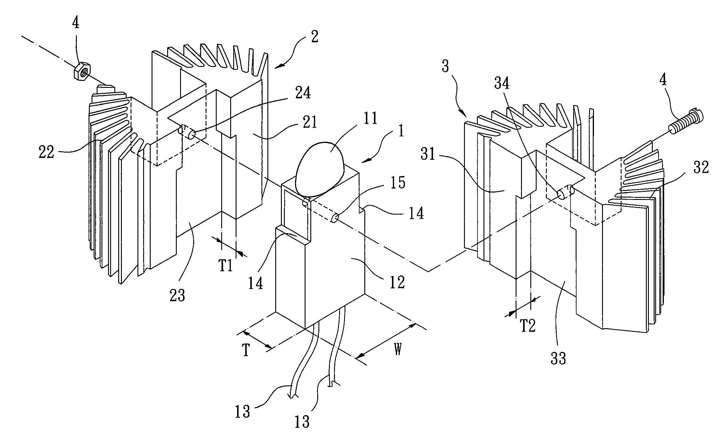
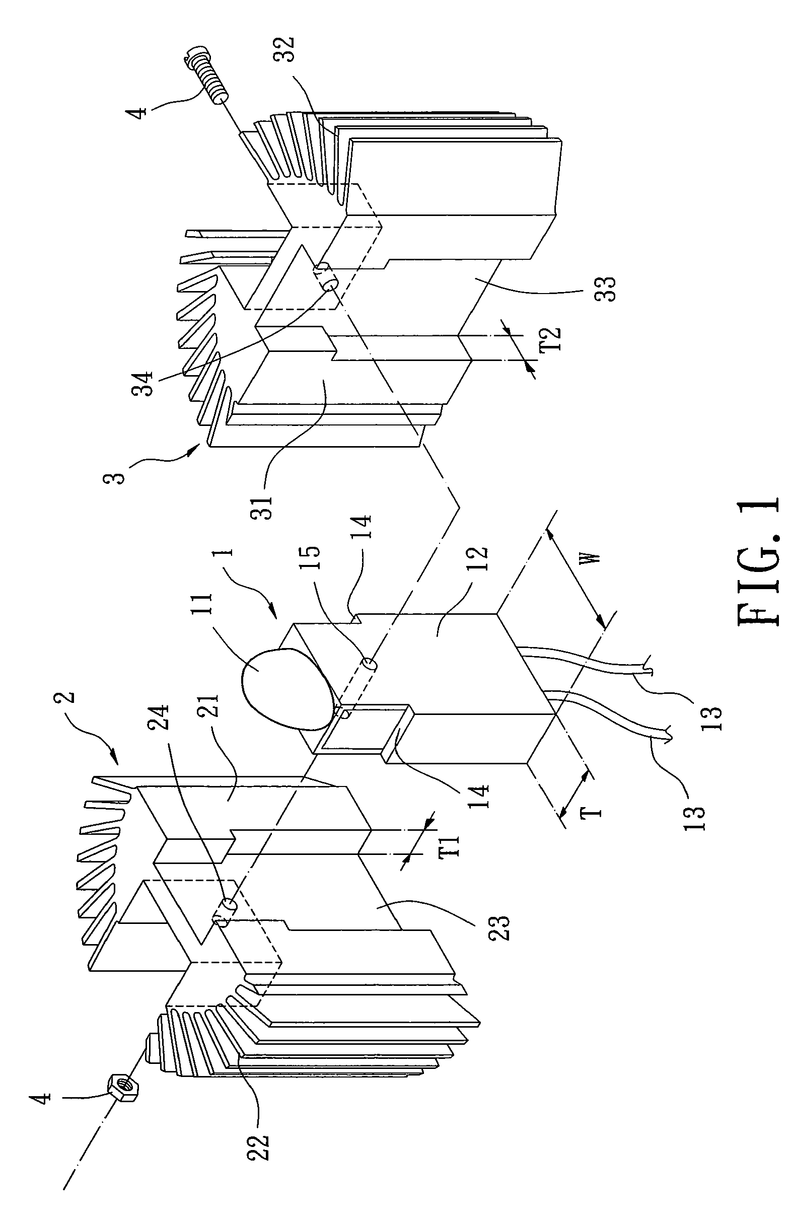
[0023]Specifically, as an example of the idea disclosed by the light emitter with heat-dissipating module mentioned above, a first embodiment according to the preferred teachings of the present invention is applied to an LED lamp, described in the following and further shown in FIGS. 1-3.

[0024]Now referring to FIG. 1, the light unit 1 includes a light-emitting element 11 selected from LEDs and a supporting plate 12 adapted for the light-emitting element 11 to be mounted to. The supporting plate 12 has a chipset therein, which connects to the light emitting-element 11, with a power line 13 being electrically connected to the chipset to energize the light-emitting element 11. The supporting plate 12 has a pair of opposite surfaces those are both preferable planes. Furthermore, the supporting plate 12 has a width “W” and a thickness “T”, wherein the width “W” is also a width of each of the opposite surfaces, and the thickness “T” is a distance between the two opposite surfaces. Optiona...

second embodiment

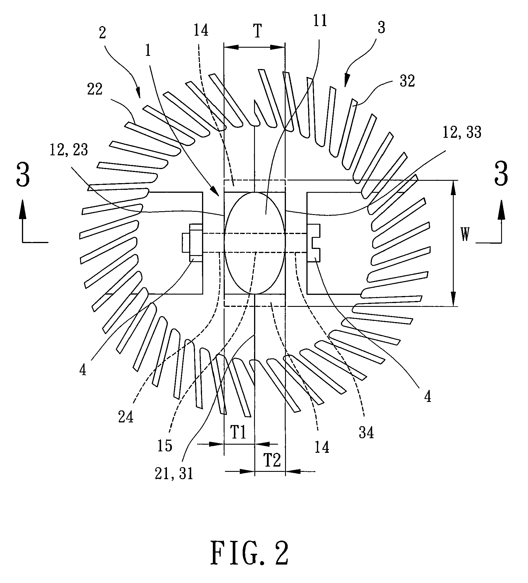
[0030]FIGS. 4 and 5 show a light emitter with heat-dissipating module of a second embodiment according to the preferred teachings of the present invention. In the preferred form shown, both of the depth “T1” of the first recess 23 of the first heat-dissipating member 2 and the depth “T2” of the second recess 33 of the second heat-dissipating member 3 are smaller than half the thickness “T” of the supporting plate 12. Although the first and second combining surfaces 21, 31 of the first and second heat-dissipating members 2, 3 doesn't touch each other while the light unit 1 and the first and second heat-dissipating members 2, 3 are combined by the fastening member 4, the first and second combining surfaces 21, 31 still firmly attach to the opposite surfaces of the supporting plate 12. Thus, an enlarged thermal conductive area is still provided for heat from the chipset of the light unit 1 to be conducted to the first and second heat-dissipating members 2, 3. Also, the first and second...

third embodiment

[0032]FIG. 6 shows a light emitter with heat-dissipating module of a third embodiment according to the preferred teachings of the present invention. In the preferred form shown, each of the first heat-dissipating member 2 and second heat-dissipating member 3 does not form any recess in the first or second combining surface 21, 31 thereof. Hence, whatever the shape of the supporting plate 12 is, the first and second heat-dissipating members 2, 3 can be mounted to it, with the supporting plate 12 having said at least two plane surfaces.

[0033]As has been discussed above, the light unit 1 and the first and second heat-dissipating members 2, 3 are combined tightly and securely to provide large thermal conductive area for the light unit 1, so that heat from the light unit 1 is transferred to the ambient environment effectively to enhance heat dissipation. Therefore, mounting a fan to the light unit 1 for heat dissipation is unnecessary to simplify the structure of the light emitter with h...


PUM


Abstract

A light emitter with heat-dissipating module includes a light unit, a first heat-dissipating member, a second heat-dissipating member and a fastening member. The light unit includes a light-emitting element and a supporting plate having a pair of opposite surfaces. The first heat-dissipating member includes a first combining surface and a heat-dissipating portion. The first combining surface contacts with one of said two opposite surfaces of the supporting plate. The second heat-dissipating member includes a second combining surface and a heat-dissipating portion. The second combining surface contacts with the other of said two opposite surfaces of the supporting plate. The fastening member couples to the supporting plate, the first heat-dissipating member and the second heat-dissipating member to fix the combination of the supporting plate and the first and second heat-dissipating members.

Description

BACKGROUND OF THE INVENTION[0001]1. Field of the Invention[0002]The present invention relates to a light emitter and, more particularly, to a light emitter including a heat-dissipating module for transmitting heat generated from a light unit of the light emitter.[0003]2. Description of the Related Art[0004]Taiwan Utility Model Publication No. M334919 entitled “Improved Structure of LED Lamp Device” is an example of a conventional light emitter with heat-dissipating module and discloses a heat sink mounted inside a housing and attaching to the back of a LED base-plate. A heat-dissipating fan is further arranged beside the heat sink, with the heat sink being arranged between the LED base-plate and the heat-dissipating fan. Thus, air can be drawn into the housing to transfer heat of the LED base-plate out of the housing.[0005]Furthermore, another conventional light emitter with heat-dissipating module is disclosed in Taiwan Utility Model Publication No. M339202 entitled “Heat-dissipati...

Claims


Application Information

Patent Timeline
Patent Type & Authority Patents(United States)
IPC IPC(8): F21V29/00
CPCF21V29/004F21V29/75F21V29/713F21V29/745F21K9/00F21Y2101/02F21Y2115/10
Inventor HORNG, ALEXMIYAHARA, MASAHARUCHUNG, CHIH-HAO
Owner SUNONWEALTH ELECTRIC MACHINE IND
Why Eureka
Try Eureka