Steering device for a ratchet screwdriver
- Summary
- Abstract
- Description
- Claims
- Application Information
AI Technical Summary
Benefits of technology
Problems solved by technology
Method used
Image
Examples
Example
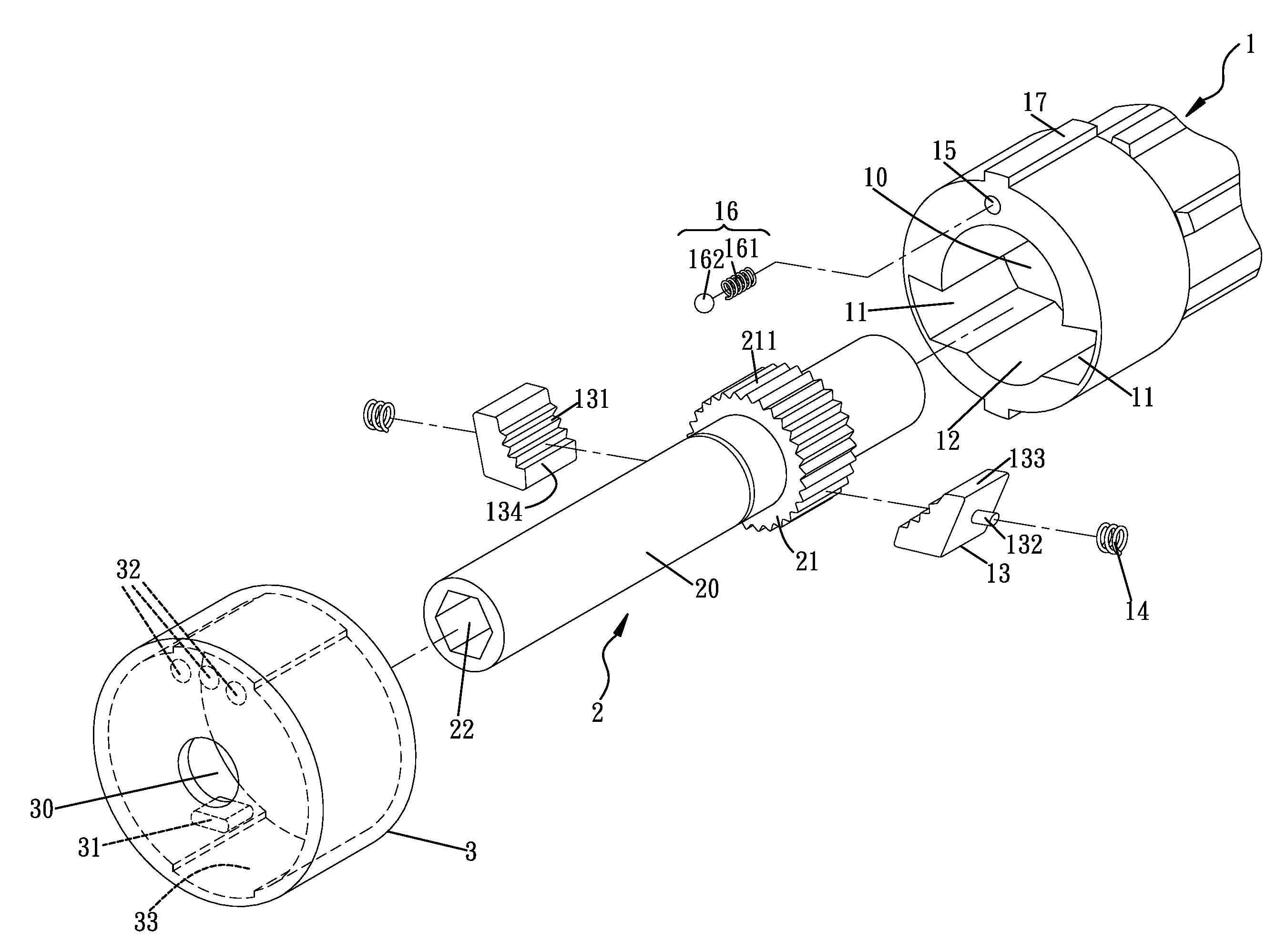
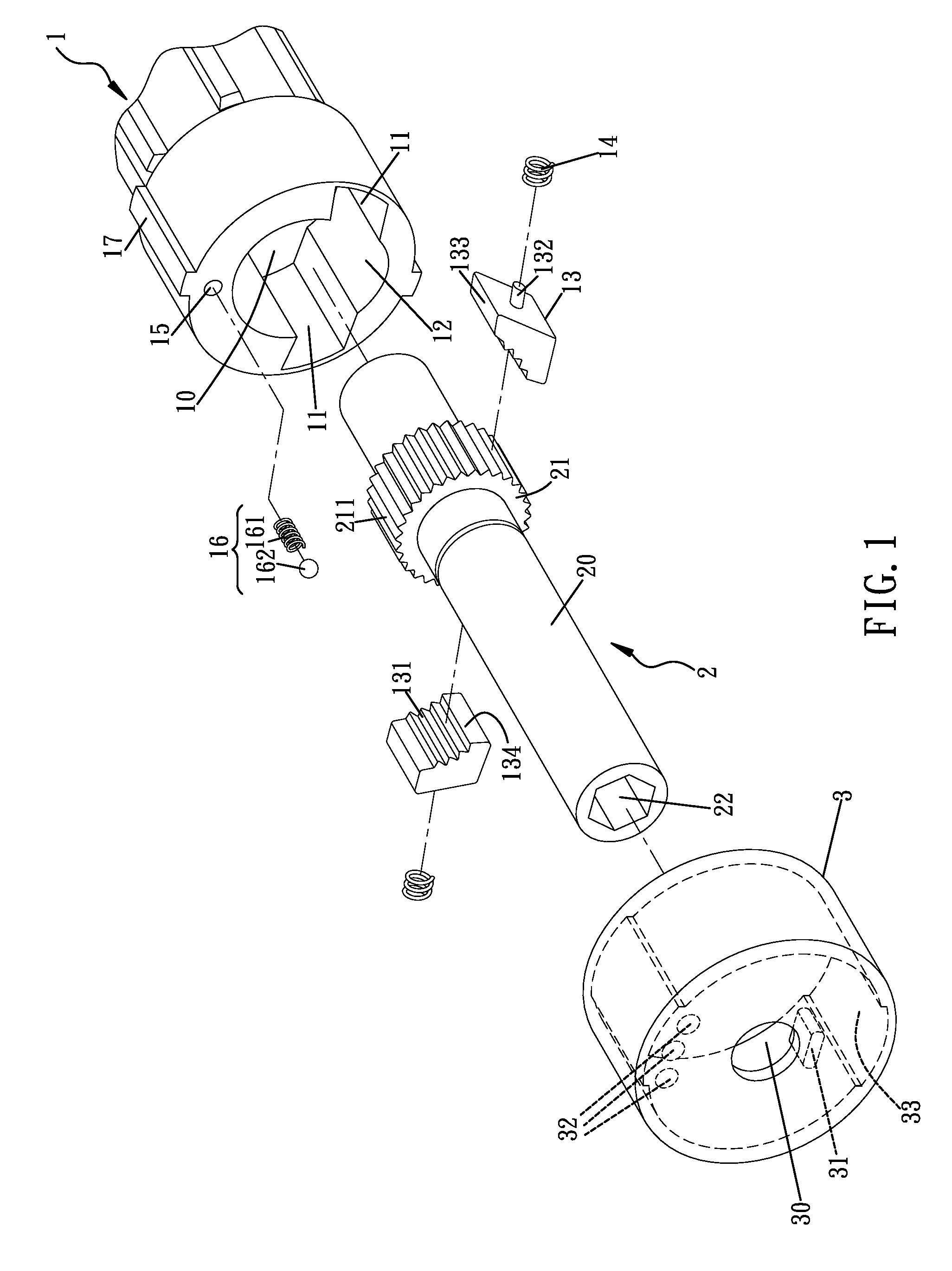
[0035]With reference to FIG. 7, that shows a second embodiment of the steering device for a ratchet screwdriver in accordance with the present invention. The elements and effects of the second embodiment which are the same with the first embodiment are not described, only the differences are described. Two receiving grooves 11 are defined in the base 1 and respectively positioned two sides of the receiving hole 10 for communicating with receiving hole 10. One receiving groove 11 (positioned in the left of FIG. 7) has a blocking wall 18 extending therefrom for dividing the receiving groove 11 into a first groove 11A and a third groove 11C. The other receiving groove 11 (positioned in the right of FIG. 7) has a blocking wall 18 extending therefrom for dividing the other receiving groove 11 into a second groove 11B and a fourth groove 11D. Two moving slots 12 are respectively comparted from receiving hole 10. One moving slot 12 (positioned in the top of the receiving hole of FIG. 7) is...
Example
[0039]With reference to FIG. 10, that shows a third embodiment of the steering device for a ratchet screwdriver in accordance with the present invention. The elements and effects of the third embodiment which are the same with the first embodiment are not described, only the differences are described. A frame 19 is mounted in the base 1 and fitted with inner peripheries of the receiving hole 10, the receiving grooves 11 and the moving slot 12. A metal material of the frame 19 is different than that of the base 1. A hardness of the frame 19 is greater than that of the base 1. In the preferred embodiment of the present invention, the base 1 is made of zinc alloy and the frame 19 is made of steel such that the frame 19 has wear-resisting effort.
Example
[0040]With reference to FIG. 11, that shows a fourth embodiment of the steering device for a ratchet screwdriver in accordance with the present invention. The elements and effects of the fourth embodiment which are the same with the second embodiment are not described, only the differences are described. A frame 19 is mounted in the base 1 and fitted with inner peripheries of the receiving hole 10, the receiving grooves 11, and the moving slots 12. The two blocking walls 18 are formed with the frame 19. A metal material of the frame 19 is different than that of the base 1. A hardness of the frame 19 is greater than that of the base 1. In the preferred embodiment of the present invention, the base 1 is made of zinc alloy and the frame 19 is made of steel such that the frame 19 has wear-resisting effort.
[0041]Although the invention has been explained in relations to its preferred embodiment, it is to be understood that many other possible modifications and variations can be made witho...
PUM
 Abstract
Description
Claims
Application Information
 - R&D
- Intellectual Property
- Life Sciences
- Materials
- Tech Scout
- Unparalleled Data Quality
- Higher Quality Content
- 60% Fewer Hallucinations
Browse by: Latest US Patents, China's latest patents, Technical Efficacy Thesaurus, Application Domain, Technology Topic, Popular Technical Reports.
© 2025 PatSnap. All rights reserved.Legal|Privacy policy|Modern Slavery Act Transparency Statement|Sitemap|About US| Contact US: help@patsnap.com


