Deployable Structure Forming an Antenna Equipped with a Solar Generator for a Satellite

a technology of solar generator and satellite, which is applied in the direction of cosmonautic vehicles, pv power plants, collapsable antennas, etc., can solve the problems of increasing the cost of missions, and increasing the size of solar panels, so as to achieve the same stacking, deployment and articulation system

Active Publication Date: 2012-12-27
THALES SA
View PDF22 Cites 16 Cited by
  • Summary
  • Abstract
  • Description
  • Claims
  • Application Information

AI Technical Summary

Benefits of technology

[0009]The invention notably has the advantage that it enables the same stacking, deploym

Problems solved by technology

Missions being increasingly “costly” in energy terms, they necessitate increasingly large solar panels.
Increasing the size of the solar panels gives rise to problems, however, both for the stowed configuration and for the operating configuration of the radar antenna.
Consequently

Method used


Image

  • Deployable Structure Forming an Antenna Equipped with a Solar Generator for a Satellite
  • Deployable Structure Forming an Antenna Equipped with a Solar Generator for a Satellite
  • Deployable Structure Forming an Antenna Equipped with a Solar Generator for a Satellite

Examples


Embodiment Construction

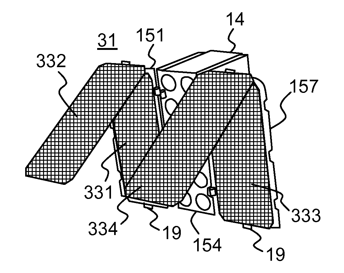
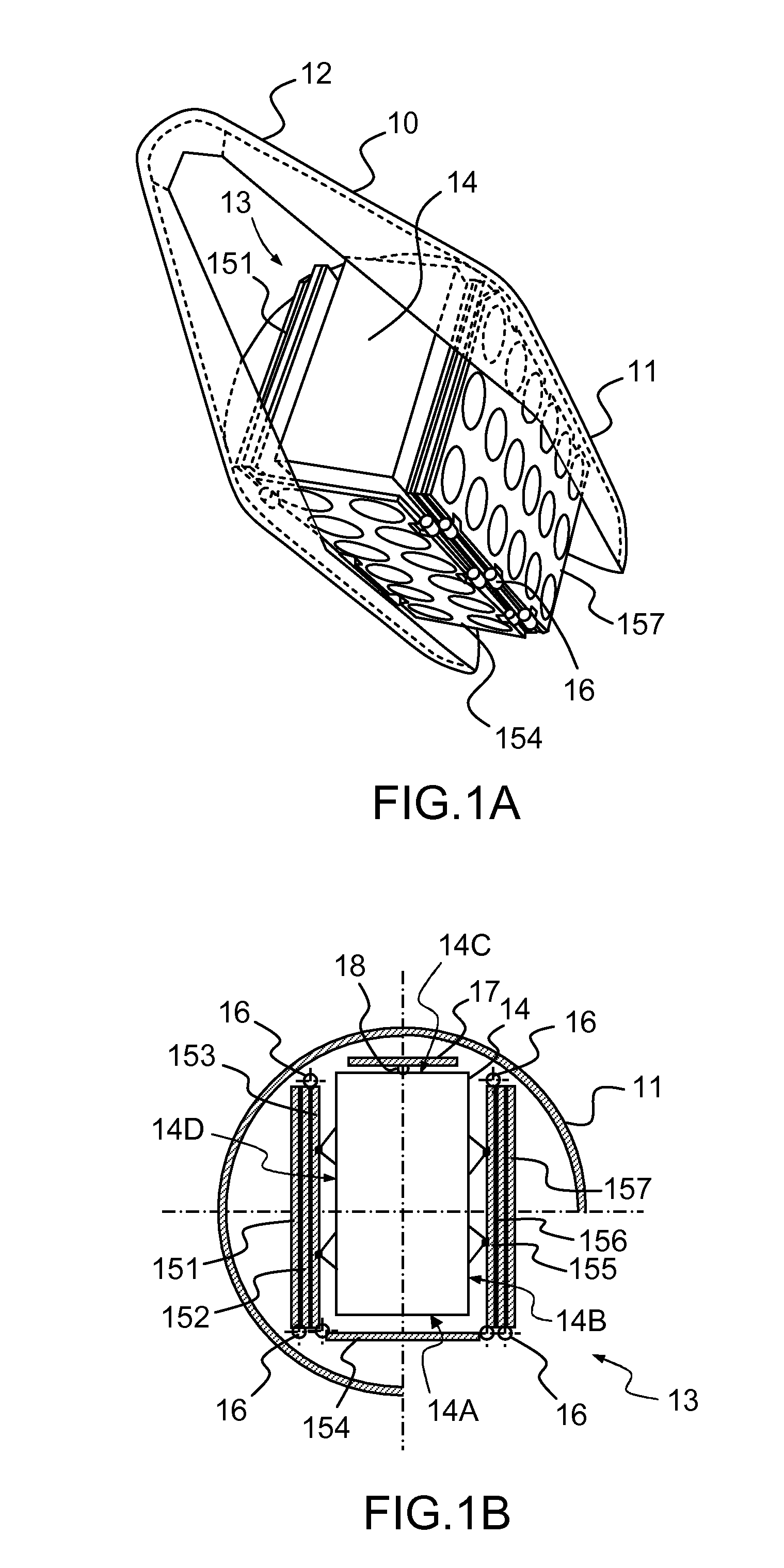
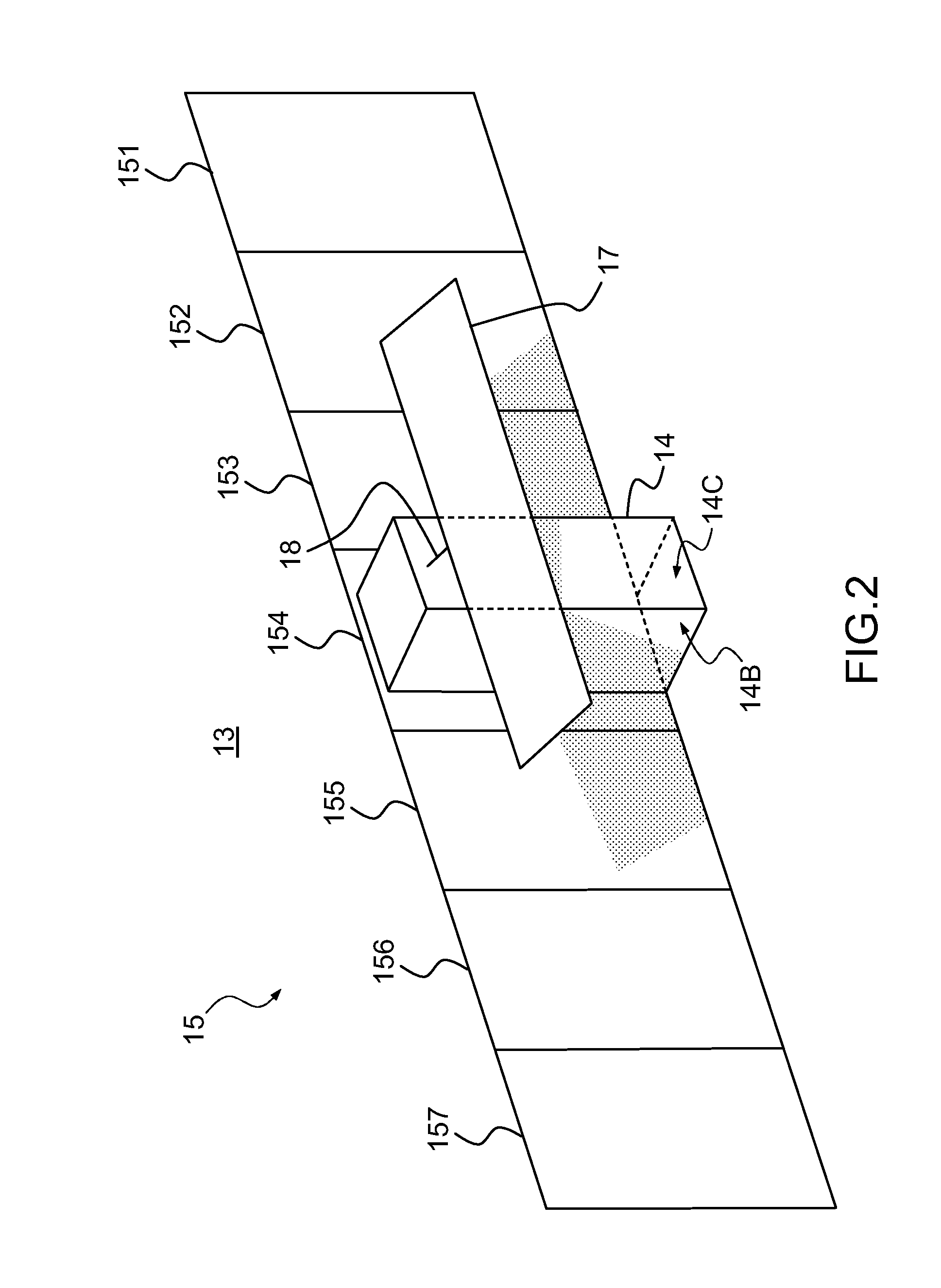
[0018]FIGS. 1A and 1B show diagrammatically, in perspective and in cross section, respectively, a launch vehicle nose cone in which is installed a satellite comprising a radar antenna in a stowed configuration. The launch vehicle nose cone 10 comprises a hollow cylindrical portion 11 and a conical portion 12. A satellite 13 is installed in the hollow cylindrical portion 11. The satellite 13 includes a body 14 of parallelepiped overall shape. The body 14 has four exterior lateral faces 14A, 14B, 14C and 14D adapted to received deployable structures. Here, the satellite 13 is equipped with a deployable antenna 15 formed of a set of antenna panels 151 to 157 articulated to each other by articulation systems 16. The antenna panels 151-157 have a substantially rectangular shape. A first antenna panel 154 is fixed to the face 14A of the body 14. The face 14A and the opposite face 14C have a width less than the faces 14B and 14D. The antenna panel 154 or, directly, the satellite 13 is conn...


PUM


Abstract

A deployable structure with panels forming an antenna equipped with a solar generator includes: a set of antenna panels each having a substantially rectangular useful surface, the antenna panels abutting each other on first sides parallel to each other, at least one photovoltaic solar panel, each photovoltaic solar panel abutting an antenna panel on a second side of said antenna panel perpendicular to the first sides, first articulation systems, each of said articulation systems enabling an antenna panel to be caused to pivot relative to an adjacent antenna panel about an axis substantially parallel to the first sides of said antenna panels, a second articulation system for each photovoltaic solar panel, each of said articulation systems enabling a photovoltaic solar panel to be caused to pivot relative to the antenna panel that it abuts about an axis substantially parallel to the second side of said antenna panel.

Description

CROSS-REFERENCE TO RELATED APPLICATION[0001]This application claims priority to foreign French patent application No. FR 1005094, filed on Dec. 23, 2010, the disclosure of which is incorporated by reference in its entirety.FIELD OF THE INVENTION[0002]The invention is situated in the field of deployable structures with which satellites may be equipped. It concerns one such deployable structure constituted of panels forming an antenna equipped with a solar generator.BACKGROUND[0003]Satellites are notably used as radar systems. To this end they include a radar antenna taking the form of a plane panel in the operating configuration. This plane panel generally has dimensions such that it cannot be placed in the operating configuration under the nose cone of the launch vehicle for placing the satellite in orbit. Consequently, a radar antenna is generally formed of a so-called deployable structure. Such a structure comprises a set of antenna panels articulated to each other in such manner ...

Claims


Application Information

Patent Timeline
IPC IPC(8): B64G1/44H01Q1/08
CPCB64G1/443B64G1/222Y02E10/50
Inventor BAUDASSE, YANNICKVEZAIN, STEPHANE
Owner THALES SA
Why Eureka
Try Eureka