
Apparatus for connecting framing components of a builiding to a foundation

Active Publication Date: 2013-01-03
HUBER ENGINEERED WOODS
View PDF9 Cites 12 Cited by
  • Summary
  • Abstract
  • Description
  • Claims
  • Application Information

AI Technical Summary

Benefits of technology

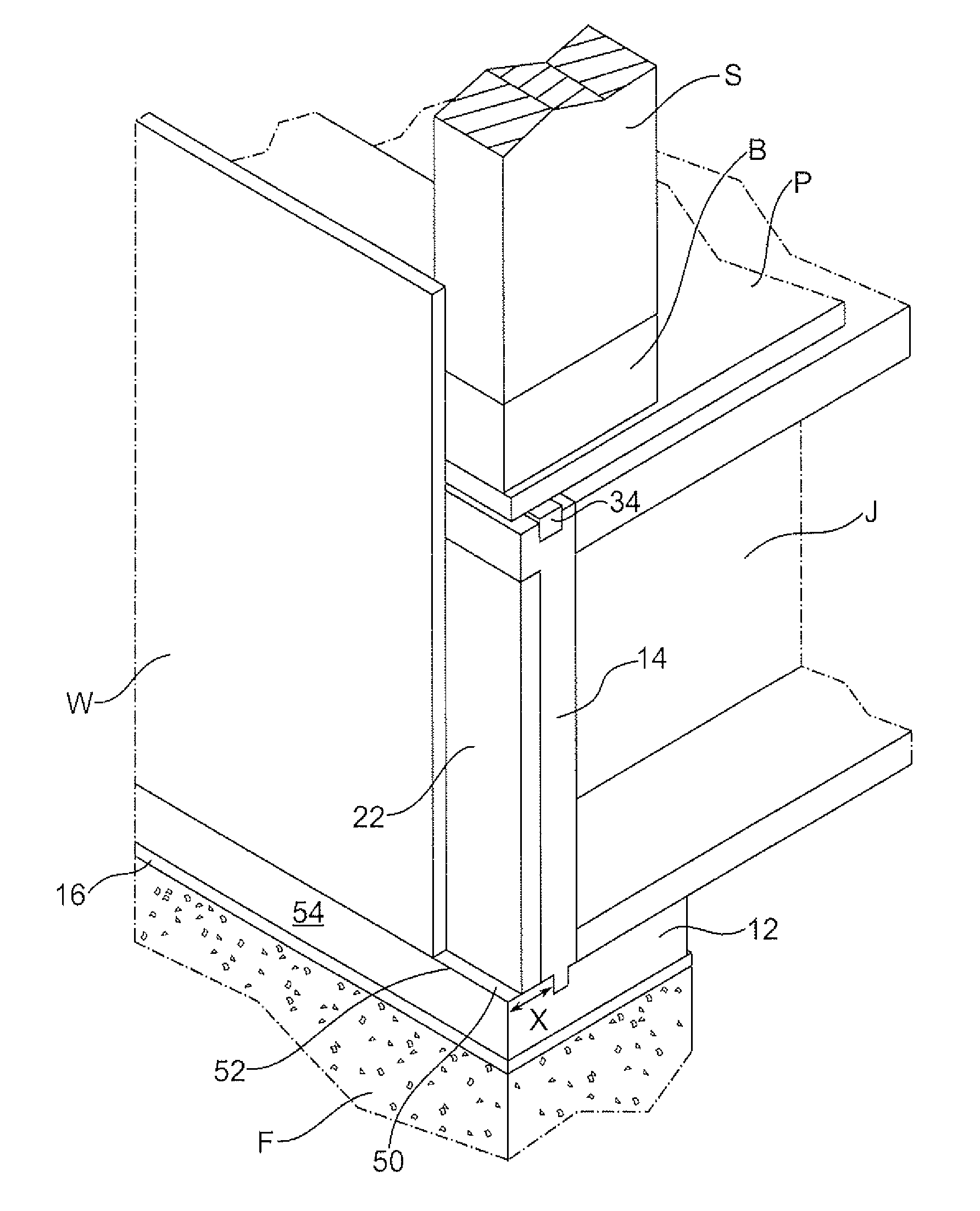
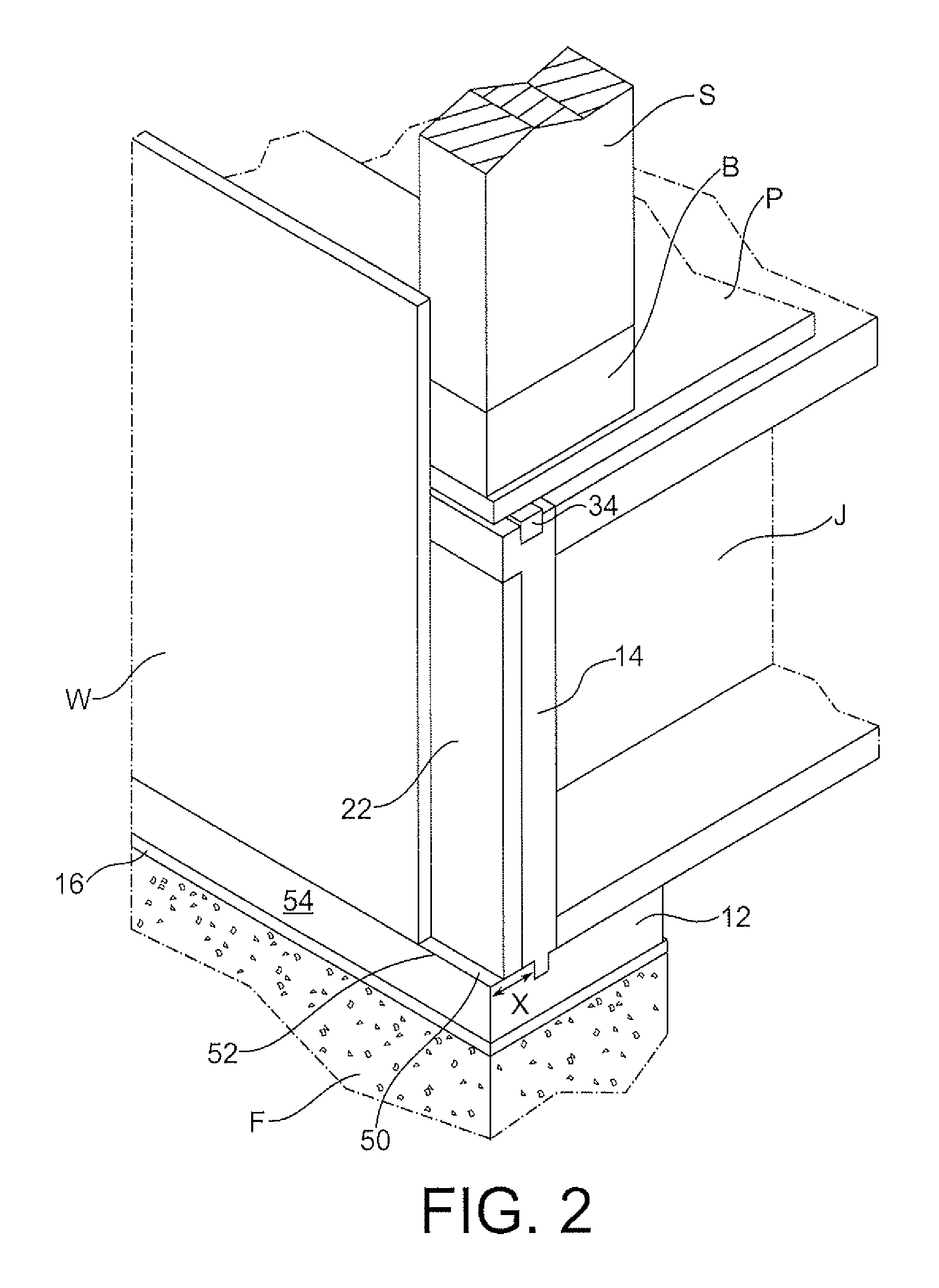
The present invention is about devices that connect framing components of a building to a foundation wall. One device is a connector with an L-shaped cross-section that is attached to the foundation wall and has a joist shelf for supporting floor joists and a recessed area where an insulation panel is adhered. Another device is a plate with joist support attached to it, where joists are located at a lower elevation than the plate when secured to the foundation wall. Another device is a plate with a perpendicular board that separates it into first and second sections, with the first section supporting wall sheathing panels and the second section supporting joists. These devices have various advantages, such as facilitating the connection of framing components to the foundation wall and providing insulation.

Problems solved by technology

Generally, the material used for the rim board is insufficiently flexible and, thus, requires fine tune adjustment to ensure planarity as it is being fastened to the joists, rim board, and adjacent rim boards.
The time it takes to make the adjustments is wasteful.
Additionally, the quality of materials for the sill plate supplied to the jobsite is often of questionable performance.
Thus, the framers typically need to sort through the supply to locate sufficient quality boards, which takes time and is wasteful both in material and labor costs.
Many times, however, the foundation is not constructed to the specifications required.
A homeowner will see the results of a foundation that is more than ⅜ inch out of level or square since these defects translate into visible quality issues of finished materials.
Moreover, minor errors at the foundation framing can be exaggerated at the top plate, and the roof trusses may not fit without manual racking.
In addition to the construction problems caused by out of level and square foundations, variations in the foundation create air-leakage points where the sill plate does not conform to the foundation.
Current sill sealing practices are insufficient to provide an air tight seal between the concrete foundation and the lower surface of the sill plate.
There are additional leak paths between the sill plate and the rim board and the top of the rim board and the bottom surface of the sub-floor that are unaddressed in most construction practices.
These leak paths allow air infiltration into the wall cavity where it greatly reduces the insulation effectiveness.
These air-leakage points can lead to significant energy losses.
Additional significant energy losses occur through conduction of heat energy through large structural member areas such as the rim board.

Method used


Image

  • Apparatus for connecting framing components of a builiding to a foundation
  • Apparatus for connecting framing components of a builiding to a foundation
  • Apparatus for connecting framing components of a builiding to a foundation

Examples


Embodiment Construction

[0022]The present invention may be understood more readily by reference to the following detailed description of the invention taken in connection with the accompanying drawing figures, which form part of this disclosure. It is also understood that this invention is not limited to the specific devices, methods and conditions or parameters described and / or shown herein, and that the terminology used herein is for the purpose of describing particular embodiments by way of example only and is not intended to be limiting of the claimed invention. Also, as used in the specification including the appended claims, the singular forms “a”, “an” and “the” include the plural, and reference to a particular numerical value indicates at least that particular value, unless the context clearly dictates otherwise. Ranges may be expressed herein as from “about” or “approximately” one particular value and / or to “about” or “approximately” another particular value. When such a range is expressed, anothe...


PUM


Abstract

An apparatus for connecting framing components of a building structure to a foundation wall includes a connector having a generally L-shaped cross-section. The connector is configured to be secured to the foundation wall. The connector has a joist shelf configured to support one or more floor joists and a ledge configured to support one or more wall sheathing panels.

Description

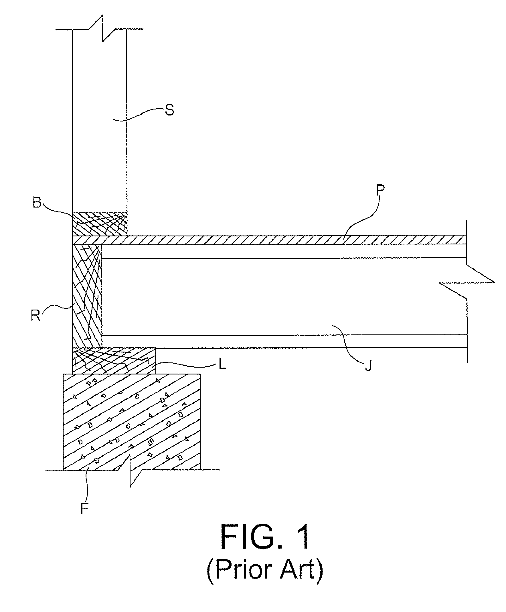
TECHNICAL FIELD[0001]The present invention is directed to an apparatus for connecting framing components of a building to a foundation.BACKGROUND[0002]The majority of buildings, including most single-family and multi-family residences and a large percentage of commercial, institutional, and public buildings constructed in the United States, are framed with wood. Light wood-frame construction adapts readily to the most intricate spaces and architectural forms. The typical platform framing technique, which is also the most common light framing construction technique, requires selecting, measuring, cutting, drilling, and assembling many components. Such components typically include a sill sealer, a sill plate, anchors, a rim board (or joist), joists, subfloor panels, and an optional termite shield.[0003]Typically, the sill plates and rim boards serve as the starting point for the remainder of the construction process, as shown in FIG. 1. The sill plate L is secured to a foundation F an...

Claims


Application Information

Patent Timeline
IPC IPC(8): E04B1/41E04B1/38E04B1/00E02D27/50
CPCE04B1/26E04B2001/2684E04B2001/268
Inventor HILL, MIKEL S.PEEK, BRIAN M.BARKER, JOEL FRANKLINHIX, KEN WILKESSALONVAARA, HARRI MIKAEL
Owner HUBER ENGINEERED WOODS
Learn More