Cable management device and server using same

a management device and server technology, applied in the direction of electrical apparatus construction details, hinge/pivot support structure mounting, support structure mounting, etc., can solve the problems of difficult management and difficulty of extra cables

Active Publication Date: 2013-01-03
FULIAN PRECISION ELECTRONICS (TIANJIN) CO LTD
View PDF13 Cites 23 Cited by
  • Summary
  • Abstract
  • Description
  • Claims
  • Application Information

AI Technical Summary

Problems solved by technology

The extra cable presents difficulties and is very difficult to manage during setup and configuration of the server since the extra cable should pass through the server casing, and the server includes many devices in the server casing blocking the passage of the cable.

Method used


Image

  • Cable management device and server using same
  • Cable management device and server using same
  • Cable management device and server using same

Examples


Embodiment Construction

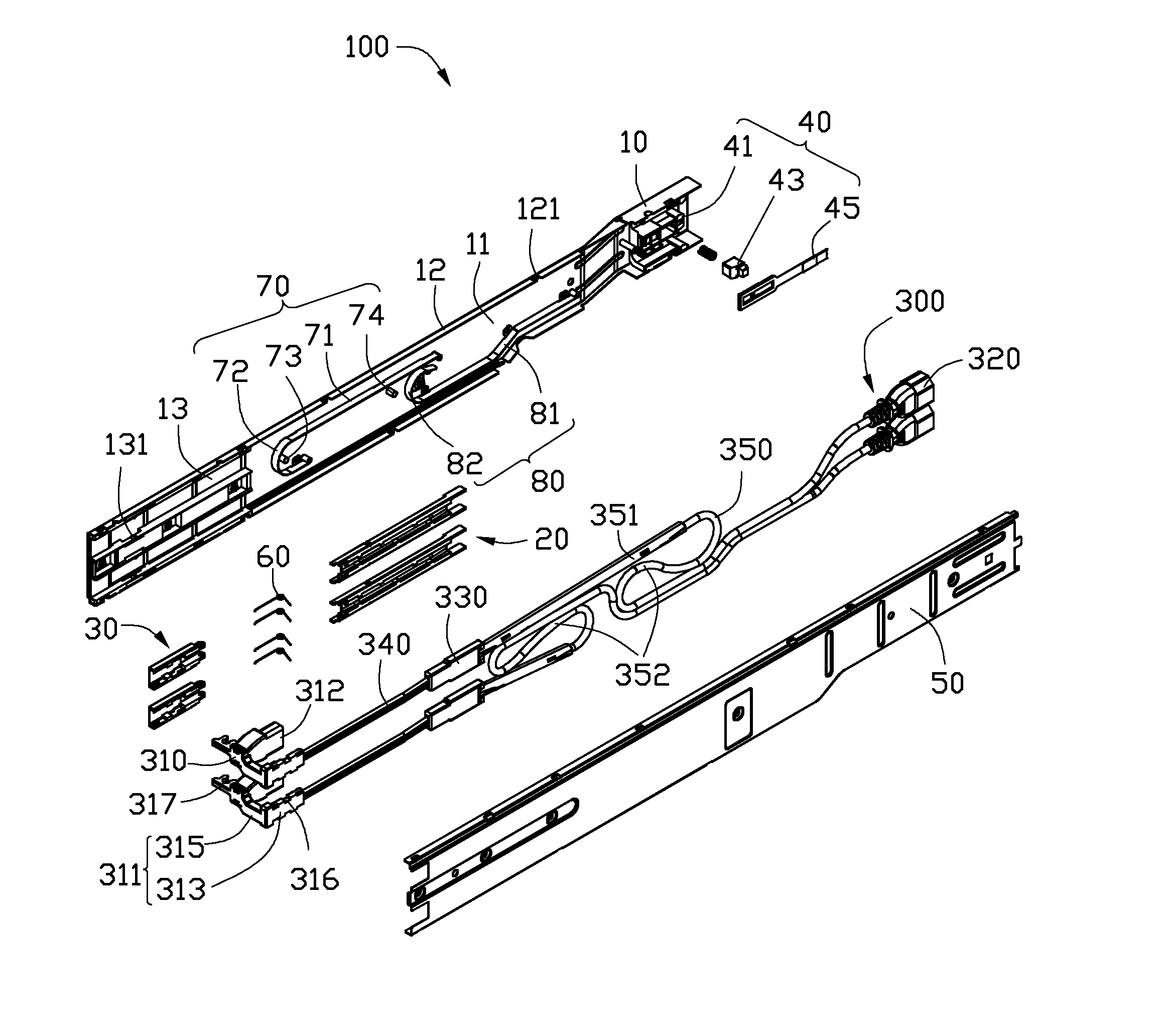
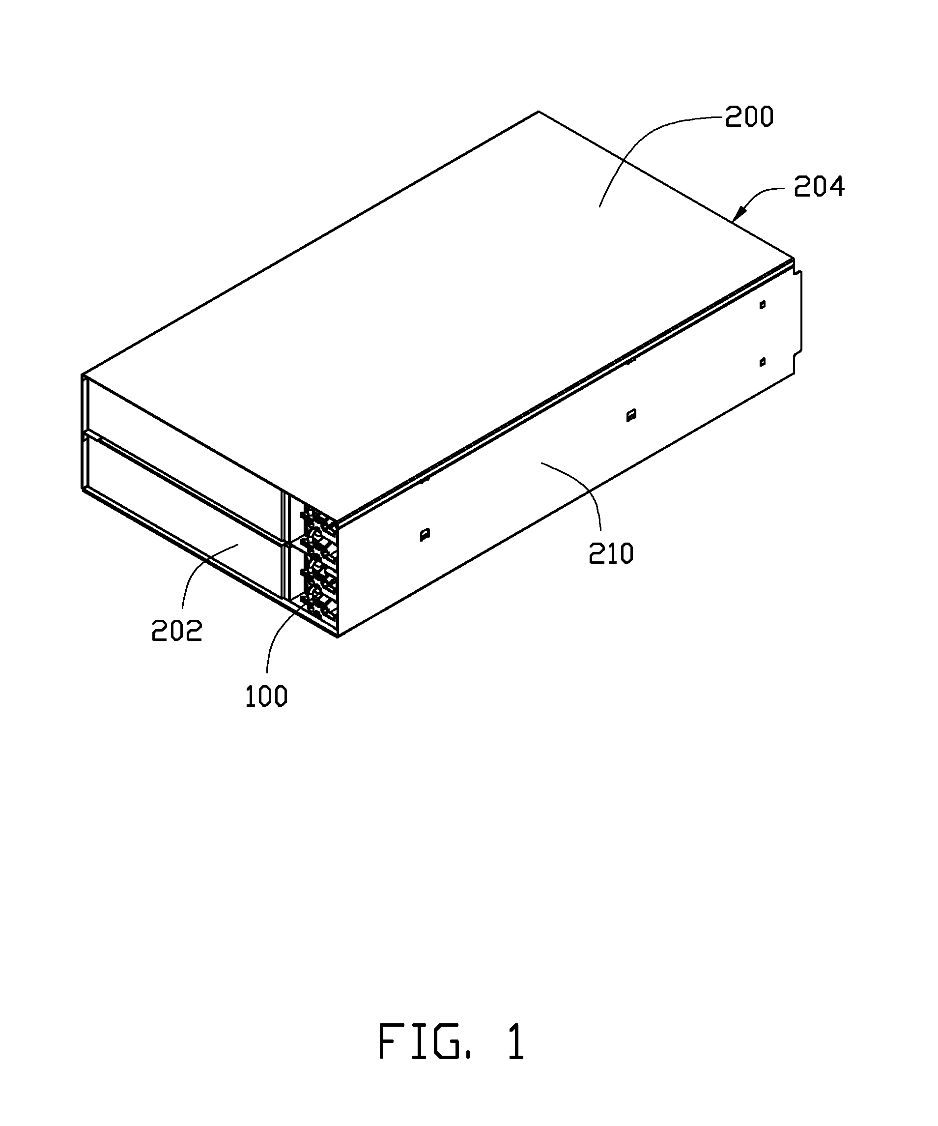
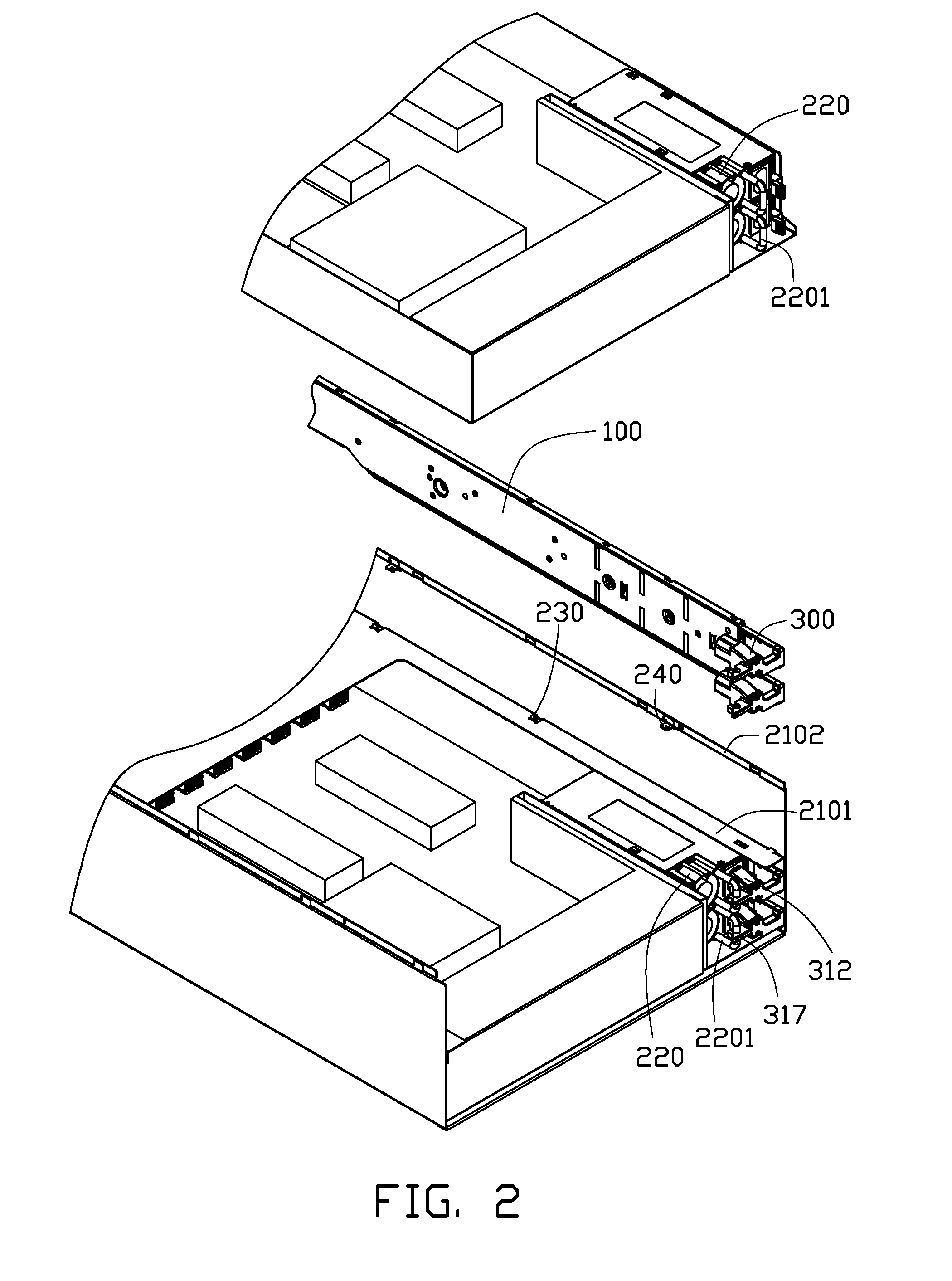
[0019]Referring to FIGS. 1 to 3, an exemplary embodiment of a server includes a server casing 200, four cable assemblies 300, and two cable assembly management devices 100 for managing the cable assemblies 300. The server casing 200 includes a front end 202, a rear end 204, a sidewall 210 and two power supplies 220. The power supplies 220 are located in the server casing 200 near or at the front end 202, and each power supply 220 is electrically connected to two of the cable assemblies 300.

[0020]Each power supply 220 includes a U-shaped operating rod 2201. The sidewall 210 includes a resisting board 2101 and two mounting ribs 2102, and the resisting board 2101 is located between the mounting ribs 2102. Each cable management device 100 and a corresponding power supply 220 are located between one of the mounting ribs 2102 and the resisting board 2101. A plurality of hooks 240 protrudes from each mounting rib 2102. A plurality of limiting plates 230 protrudes from the resisting board 2...


PUM


Abstract

A cable management device includes a shell, a driving assembly and a cover. The shell includes a first coil winder and a second coil winder. The driving assembly is slidably fixed to the shell, the driving assembly including a sliding rack and a rotating rack. The cover is releasably latched to the shell. The cable assembly includes a first end, a second end and a coil section. The first end is fixed to the driving assembly, the second end is fixed to the shell. The coil section is wound onto the first coil winder and the second coil winder. When the driving assembly is slid out of the shell, the driving assembly stretches the coil section, and the rotating rack rotates relative to the sliding rack, bending the cable assembly.

Description

BACKGROUND[0001]1. Technical Field[0002]This disclosure relates to cable management devices, and in particular, to a cable management device for a server.[0003]2. Description of Related Art[0004]A server may include a server casing and a power supply located at a rear portion of the server casing. The power supply is connected to an outer power source to supply electric energy to the server. However, the power supply would be located somewhere at the front portion of the server casing. In this condition, the server needs an extra cable passing through the server from the front portion to the rear portion, to connect the power supply and the outer power source. The extra cable presents difficulties and is very difficult to manage during setup and configuration of the server since the extra cable should pass through the server casing, and the server includes many devices in the server casing blocking the passage of the cable.[0005]Therefore, there is a room for improvement in the art....

Claims


Application Information

Patent Timeline
Patent Type & Authority Applications(United States)
IPC IPC(8): H05K7/16H02B1/20
CPCH05K7/1491H01R13/72
Inventor GONG, XIN-HUSHU, SI-WENDAI, JU-WEN
Owner FULIAN PRECISION ELECTRONICS (TIANJIN) CO LTD
Why Eureka
Try Eureka