
Wireless takeover of an alarm system

a technology of alarm system and wired control panel, which is applied in the direction of electric signalling details, signalling systems, instruments, etc., can solve the problems of additional wiring, limited ability of wireless control panel to connect passive wired sensors, and additional wires

Active Publication Date: 2013-01-10
NICE NORTH AMERICA LLC
View PDF1 Cites 10 Cited by
  • Summary
  • Abstract
  • Description
  • Claims
  • Application Information

AI Technical Summary

Benefits of technology

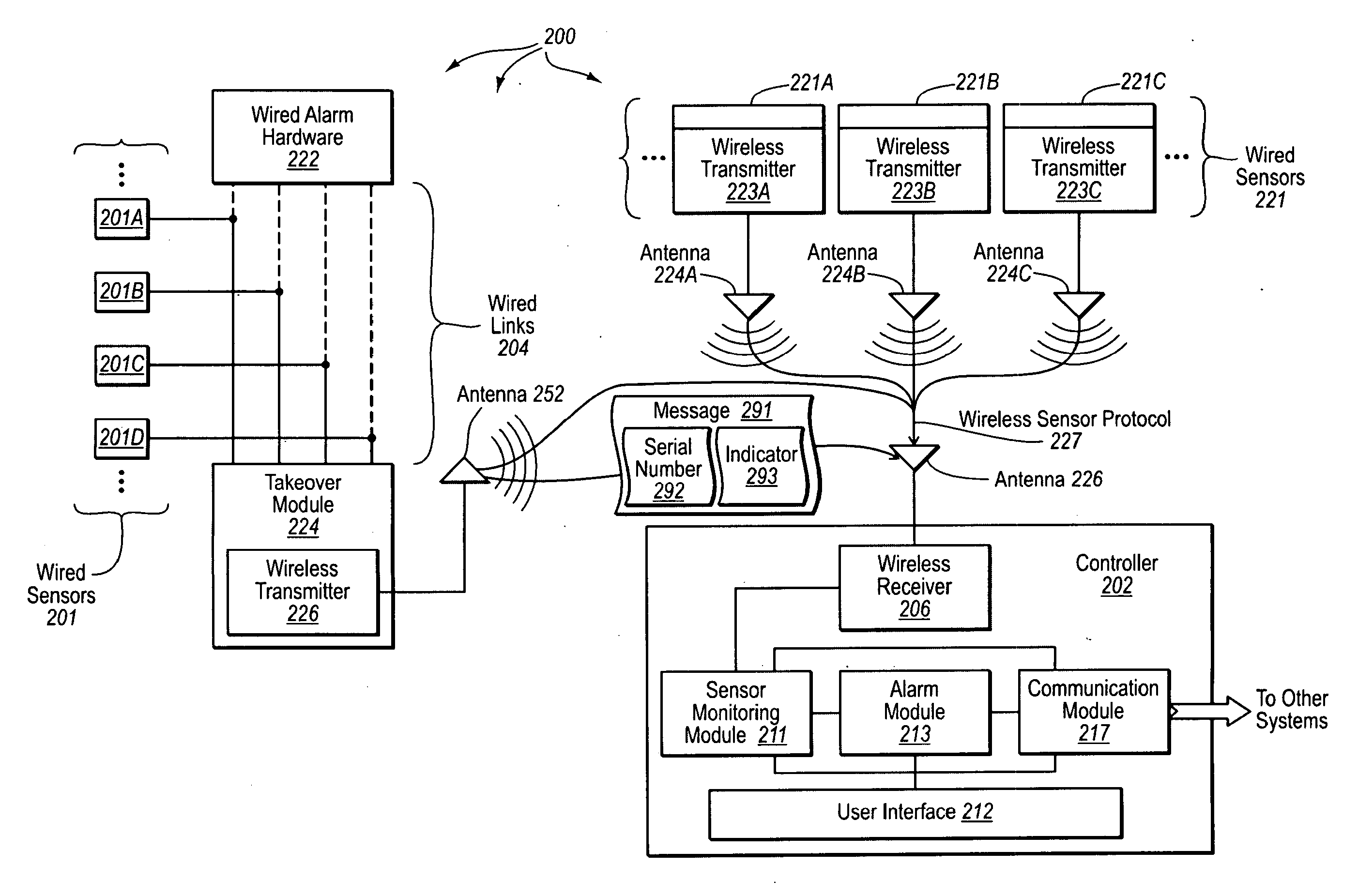
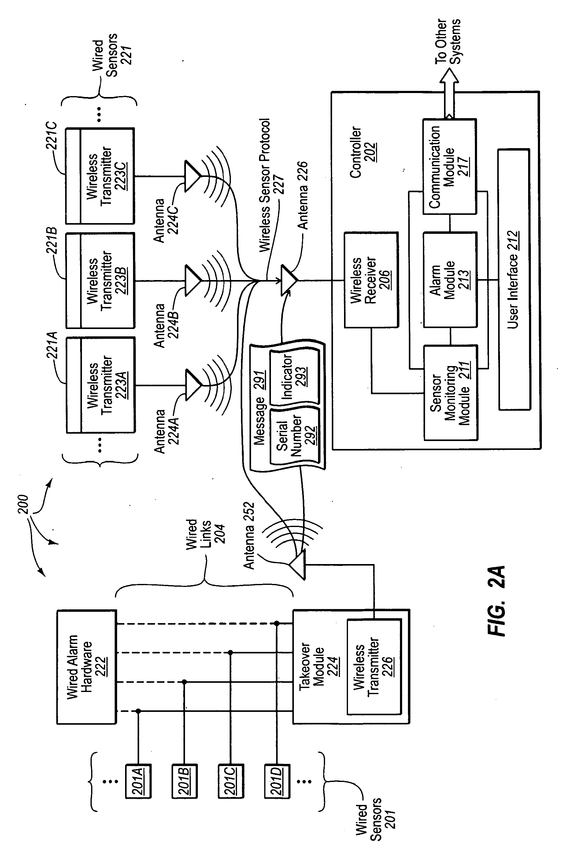
The patent describes a wireless system that allows for the transmission of alarm data from sensors to a central control unit. This is done through a wireless transmitter that sends the data to the control unit using a compatible frequency and wireless sensor protocol. This means that the wireless alarm controls can appear to be receiving input from wireless sensors. Overall, the system allows for a more seamless and wireless connection between the sensors and the control unit.

Problems solved by technology

Since emitting energy into a surrounding area consumes power, additional wiring is typical required connecting active sensors to a wired power source.
However, some wireless control panels do provide limited capability to connect passive wired sensors (e.g., providing one or two connections for passive wired sensors).
However, installing new wired sensors requires running additional wires, which can be time consuming and costly.
Unfortunately, it can be problematic to supplement an existing hardwired alarm system (e.g. that already includes a number of wired sensors) with additional wireless sensors.
Some existing wired control panels are not compatible with wireless sensors and wireless sensor protocols.
However, switching to a wireless control panel significantly limits (and depending on the wired control panel potentially eliminates) the use of existing wired sensors.
Thus, when considering how to supplement an existing wired alarm system with addition sensors, a user is often forced to make a difficult choice.
However, choosing to use additional wired sensors results in the time and cost burdens associated with running additional wiring.
However, choosing to use wireless sensors typically requires replacement of an existing wired control panel with a wireless control panel.
Replacement of the existing wired control panel can result in loss of functionality for many wired sensors (due either to sensor type or number of sensors).

Method used


Image

  • Wireless takeover of an alarm system
  • Wireless takeover of an alarm system
  • Wireless takeover of an alarm system

Examples


Embodiment Construction

[0028]The present invention extends to methods, circuits, and systems for wireless takeover of wired alarm system components. Embodiments of the invention include an alarm system comprising wired alarm hardware, such as, for example, a wired alarm controller. The wired alarm hardware is configured to receive wired sensor input from a plurality of connected wired alarm sensors. One or more wires connect each wired sensor to the wired alarm hardware.

[0029]The alarm system also includes a takeover module. The takeover module includes external connections, a microprocessor, and a wireless transmitter. The external connections are configured to connect to the one or more wires connected to each wired alarm sensor. Accordingly, wired sensor input from the wired alarm sensors (including alarm conditions) is received at the external connections. The microprocessor is configured to receive wired sensor input from the wired alarm sensors over the external connections. The microprocessor is al...


PUM


Abstract

The present invention extends to methods, systems, and computer program products for wireless takeover of wired alarm system components. Embodiments of the invention can be used to bridge hardwired alarm zones for use with a wireless alarm controller. Wired sensors are wired to a takeover module that converts communication from the wired sensors into wireless communication that can be compatibly processed at an alarm controller that accepts wireless signals. Power and ground connections from an existing wired alarm controller can be used with the takeover module to facilitate wireless takeover of wired alarm sensors.

Description

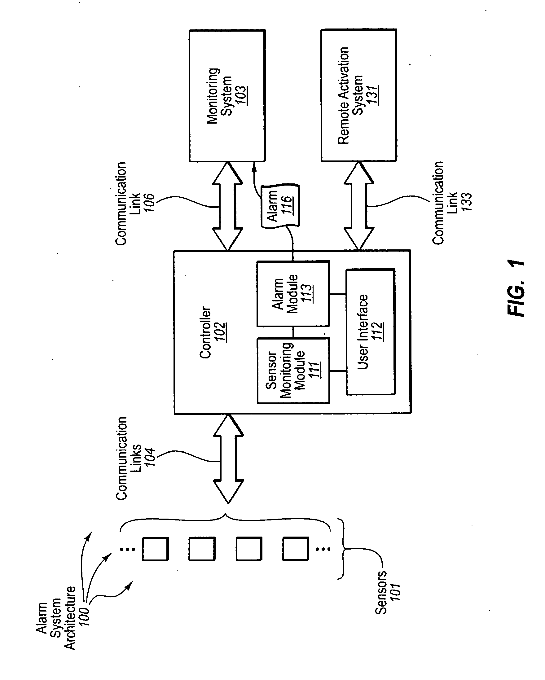
CROSS-REFERENCE TO RELATED APPLICATIONS[0001]This application is a continuation of U.S. patent application Ser. No. 12 / 480,369, filed on Jun. 8, 2009, and titled “WIRELESS TAKEOVER OF WIRED ALARM SYSTEM COMPONENTS” (hereinafter “the '369 Application”). The entire disclosures of the '369 Application are, by this reference, hereby incorporated herein.BACKGROUND[0002]Many homeowners and businesses use an alarm system to protect their real and personal property. An alarm system can be used to detect physical disturbances on a premise and alert an owner and / or authorities about the physical disturbance. An alarm system can be a stand alone system or integrated within a larger security system context (e.g., that also includes armed guards, CCTV, etc.)[0003]A typical alarm system includes a number of sensors linked to a control panel. The control panel includes an interface that can be used by a human user to arm, or in many cases activate monitoring (e.g., when leaving their residence) an...

Claims


Application Information

Patent Timeline
Patent Type & Authority Applications(United States)
IPC IPC(8): G08B23/00
CPCG08B29/16G08B25/10
Inventor SIMON, SCOTT HARRISDEAN, LANCE LEO
Owner NICE NORTH AMERICA LLC
Learn More