
Display system and method

Inactive Publication Date: 2013-01-31
HON HAI PRECISION IND CO LTD
View PDF2 Cites 13 Cited by
  • Summary
  • Abstract
  • Description
  • Claims
  • Application Information

AI Technical Summary

Benefits of technology

The present patent is about a display system that allows multiple electronic devices to display a whole-image, even if they have small size display screens. The system includes a master electronic device and a slave electronic device that communicate with each other through wired or wireless connections. The slave electronic device has a display unit, sensors, and a processor to detect the position of the master electronic device and adjust the display accordingly. The master electronic device has a display unit, sensors, and a processor to detect the position of the slave electronic device and adjust the display accordingly. The system allows for a united display with a larger display area, and the display units can be united together to form a single display. The technical effect of the patent is to provide a display system that allows for seamless viewing of high definition images on multiple electronic devices with small display screens.

Problems solved by technology

However, for an electronic device with a small size display screen, displaying a high definition image is often limited.
Although a zoom option can be selected to enlarge the image to view the detail of the image, the image can not be viewed integrally.

Method used


Image

  • Display system and method
  • Display system and method
  • Display system and method

Examples


Embodiment Construction

[0013]The embodiments of the present disclosure are now described in detail, with reference to the accompanying drawings.

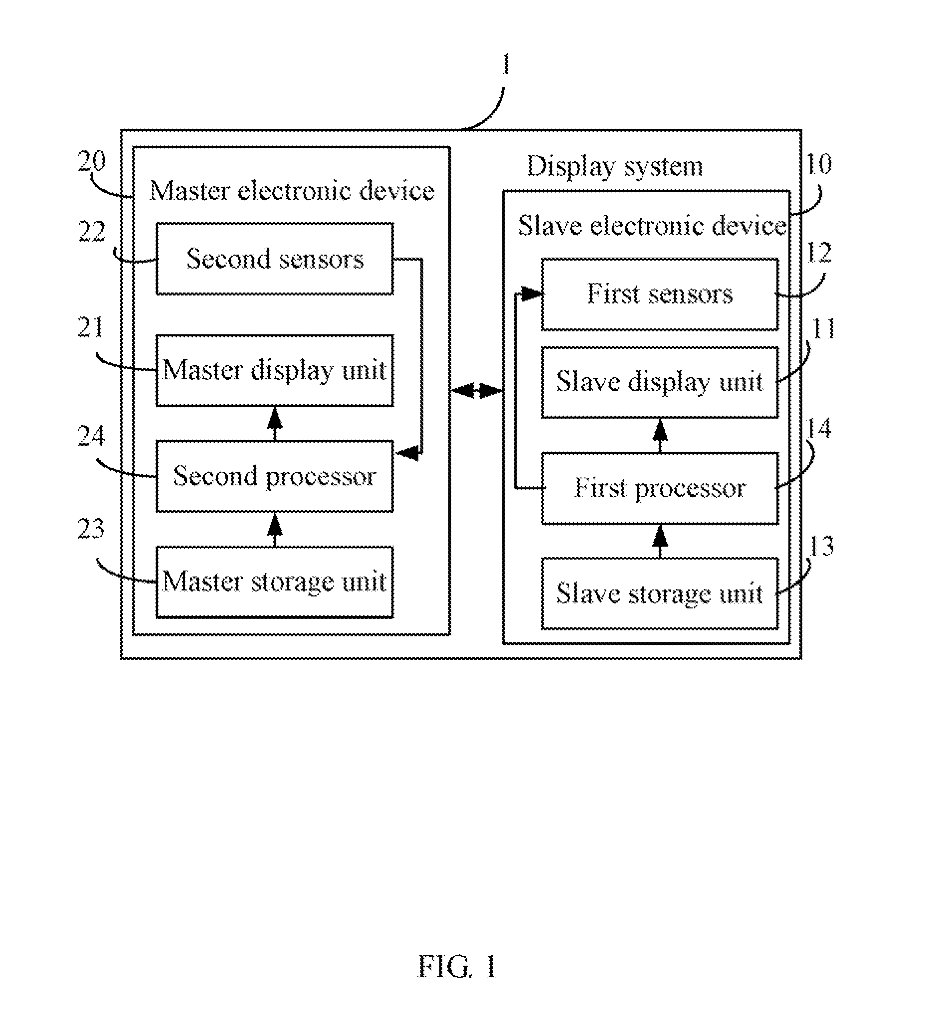
[0014]Referring to FIGS. 1-2, a block diagram of a display system 1 in accordance with an exemplary embodiment is shown. The display system 1 includes at least one slave electronic device 10 and a master electronic device 20. The master electronic device 20 and the at least one slave electronic device 10 cooperatively display an image. For the simplicity, only one slave electronic device 10 is described hereinafter. The slave electronic device 10 communicates with the master electronic device 20 through a wired or wireless connections. In the embodiment, the slave electronic device 10 and the master electronic device 20 may be a device with a small display unit, such as mobile phones, PDAs, for example.

[0015]The slave electronic device 10 includes a slave display unit 11, a number of first sensors 12, a slave storage unit 13, and a first processor 14.

[0016]The mas...


PUM


Abstract

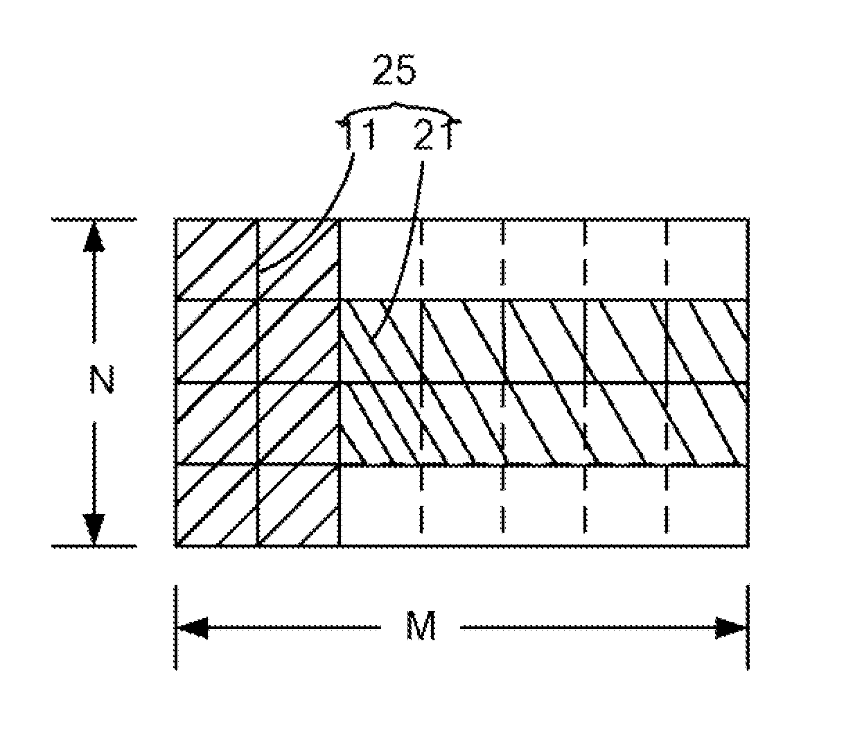
An exemplary electronic device is capable of communicating with one other electronic device including a slave display unit. The electronic device includes a master display unit, sensors, and a processor. The master display unit and the at least one slave display unit cooperatively form a united display unit. The master display unit has sub-display areas. The sensors are arranged on the master display unit. The processor determines the position of the slave display unit relative to the master display unit according to the sensors, establish a minimum virtual display area M×N, and determine maximum actual rectangle display area m×n that the united display unit has. The processor further divides an image to m×n sub-images, transmit the sub-images displayed by the slave display unit to the another electronic device, and further control the master display unit to display the determined sub-images.

Description

BACKGROUND[0001]1. Technical Field[0002]The present disclosure relates to display systems and, particularly, to a display system having multiple electronic devices to display a whole-image, an electronic device, and a display method.[0003]2. Description of Related Art[0004]Displaying a high definition image often needs a large display screen. However, for an electronic device with a small size display screen, displaying a high definition image is often limited. Although a zoom option can be selected to enlarge the image to view the detail of the image, the image can not be viewed integrally. Thereby, a display system having a larger size display screen is desired.BRIEF DESCRIPTION OF THE DRAWINGS[0005]The components of the drawings are not necessarily drawn to scale, the emphasis instead being placed upon clearly illustrating the principles of the present disclosure. Moreover, in the drawings, like reference numerals designate corresponding parts throughout several views.[0006]FIG. ...

Claims


Application Information

Patent Timeline
IPC IPC(8): G09G5/00
CPCG06F3/1446G09G2356/00G09G2340/0407
Inventor CHU, TING-TING
Owner HON HAI PRECISION IND CO LTD
Learn More