Systems and Methods for Long Endurance Airship Operations

a technology of airships and airframes, applied in balloon aircrafts, convertible aircrafts, vehicles, etc., can solve the problems of increasing the risk of damage or loss of aircraft and payload, increasing the cost and risk of aircraft damage or loss, and reducing the aerodynamic force. , the effect of minimizing the requirements for operating and/or stationkeeping power

Active Publication Date: 2013-02-14
STRATOSPHERIC AIRSHIPS
View PDF19 Cites 117 Cited by
  • Summary
  • Abstract
  • Description
  • Claims
  • Application Information

AI Technical Summary

Benefits of technology

[0008]The combined airship may include an upper airship at a first altitude and a lower airship at a second altitude, the upper and lower airships being connected by a tether, in which the first altitude and second altitude are stratospheric altitudes that are vertically separated by at least five kilometers. Maintaining stationkeeping at a station involves altering the aerodynamic characteristics of at least one of the airships to improve the stationkeeping performance of the tethered airship system. This may be done in a variety of ways. When the winds at the first altitude and winds at the second altitude are traveling in substantially different directions, altering the aerodynamic characteristics of the combined airship may include at least one of: altering the heading of one of the airships, deploying a parachute, altering aerodynamic characteristics of the parachute, deploying a parafoil, altering the aerodynamic characteristics of the parafoil, changing at least one of the first attitude and the second attitude, or other suitable change, such as altering the attachment point of the tether or altering the attitude of one or more of the airships. These methods may also be used to maneuver the combined airship from one location to another, restore position at a desired station, or even follow a desired route. With winds operating primarily in an east-west direction (and in substantially different directions at the first altitude and second altitude), east-west maneuvering can be performed by adjusting the drag of the two airships (by e.g. altering the aerodynamic characteristics of the parachutes). North-south maneuvering can be performed by adjusting the aerodynamic characteristics of the parafoils, so that the lift vectors of the parafoils, considered together, provide a net northward or southward component. Vertical maneuvering, within the limits of the combined airship's design, can be performed by adjusting the length of the tether as well as by altering the aerodynamic characteristics of the parafoils, so that the lift vectors of the parafoils, considered together, provide a net upward or downward component.
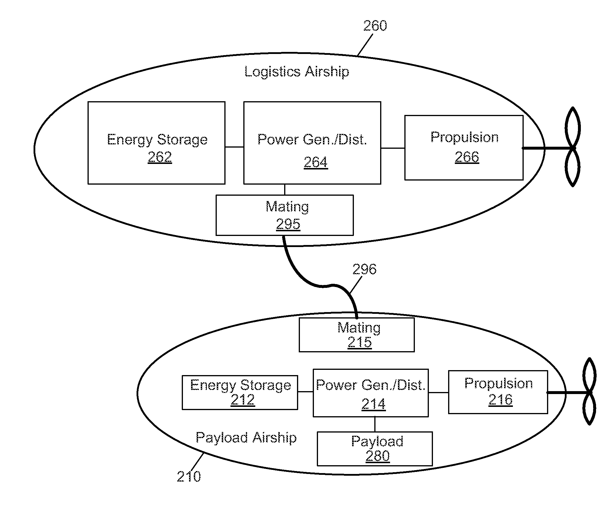
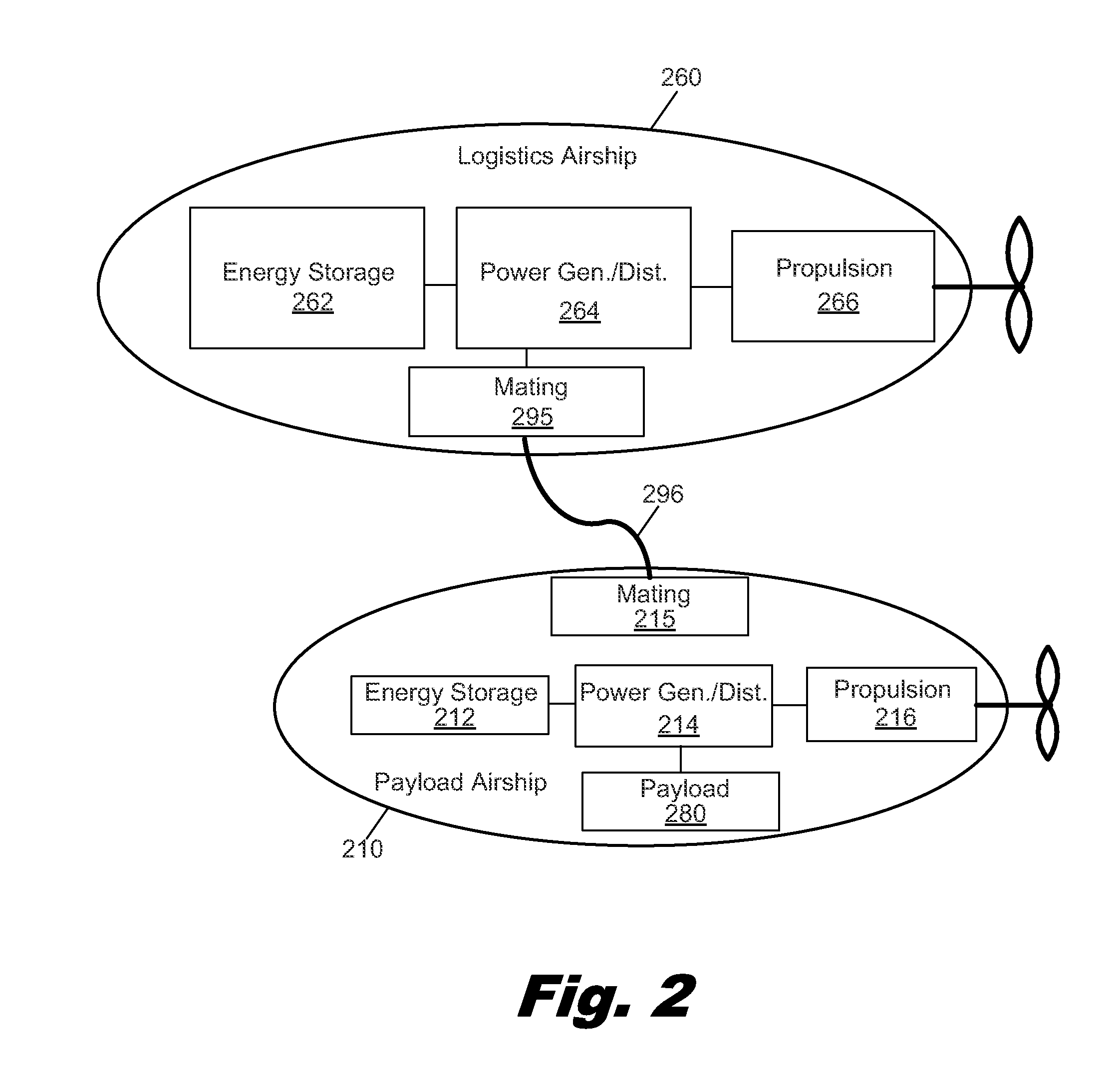
[0023]Thus, one embodiment of an illustrative method for long term stratospheric airship operations may include deploying a lower airship connected to an upper airship by a tether with a shuttle running along the tether to deliver lifting gas to the upper airship. Resupplying lifting gas to the upper airship from the lower airship via the shuttle uses a supply of lifting gas stored in a gas reservoir in the lower airship. A payload may be delivered to the lower airship using a logistics tug and returning the logistics tug to the ground. Airship operation may be continued until the reservoir of lifting gas reaches a predetermined depletion level and then the logistics tug is dispatched to resupply lifting gas to the lower airship. Additionally, the logistics tug may resupply fuel to the lower airship. The method may also include selecting operational altitudes for the lower airship and upper airship such that wind forces on the lower airship are in a substantially different direction than wind forces on the upper airship and / or adjusting lift and drag compensation between the lower airship and upper airship to minimize operating and / or stationkeeping power requirements.

Problems solved by technology

However, current aircraft have limited endurance for free-flight operations, whether those operations involve flight over an extended route, or stationkeeping at a station, or a combination of the two.
This can be both expensive and hazardous.
The take off and landing of aircraft are typically the highest risk portions of a mission, and each takeoff and landing increases the risk of damage or loss of the aircraft and payload.
This is particularly true for lighter-than-air aircraft that tend to be large and relatively slow-moving.

Method used


Image

  • Systems and Methods for Long Endurance Airship Operations
  • Systems and Methods for Long Endurance Airship Operations
  • Systems and Methods for Long Endurance Airship Operations

Examples


numerical example

[0347]This section provides an exemplary sizing exercise for one embodiment of the inventive concept. It is not intended as a final or refined point design, which in any case would require a detailed consideration of currently-available materials and construction techniques, as well as detailed simulations of intended missions in the intended environments; instead, it is intended to expose some of the design considerations and tradeoffs particularly involved in the inventive concept.

[0348]For this sizing exercise, the payload airship, and the shuttle intended to resupply lifting gas to the upper airship, are assumed to be roughly spherical in shape. The payload airship is assumed to be mated to the front (or bow) of the lower airship 2310. As a consequence, the payload airship does not support a parachute. Instead, the lower airship 2310 supports both a parachute and a parafoil generally consistent with the concepts described in FIGS. 16-18.

[0349]The payload airship is sized first. ...


PUM


Abstract

In one example, a long endurance airship system includes a payload airship and a first logistics airship mechanically joined to the payload airship to form a first combined airship, the payload airship and the logistics airship having design capabilities differing by at least a factor of two with regard to at least one of: power generation capability, propulsion capability, endurance capability, and lift capability, in which the first combined airship is free flying, lighter-than-air, and configured to maintain aloft for greater than 30 days without physical connection to the ground. Illustrative methods for long endurance airship operations are also provided.

Description

RELATED APPLICATIONS[0001]The present application is a continuation-in-part, and claims the benefit under 35 U.S.C. §120, of U.S. application Ser. No. 13 / 228,212, filed Sep. 8, 2011, which claims the benefit under 35 U.S.C. §120 of U.S. application Ser. No. 13 / 159,215, filed Jun. 13, 2011 and U.S. application Ser. No. 13 / 048,625, filed Mar. 15, 2011. The present application is also a continuation-in-part, and claims the benefit under 35 U.S.C. §120, of U.S. application Ser. No. 13 / 227,966, filed Sep. 8, 2011, which also claims the benefit under 35 U.S.C. §120 of U.S. application Ser. No. 13 / 159,215, filed Jun. 13, 2011 and U.S. application Ser. No. 13 / 048,625, filed Mar. 15, 2011. These applications are hereby incorporated by reference in their entireties.BACKGROUND[0002]There is a recognized need for long endurance aeronautical operations that can, for example, provide persistent surveillance, maintain a communication link, or make in situ science measurements over an extended peri...

Claims


Application Information

Patent Timeline
Patent Type & Authority Applications(United States)
IPC IPC(8): B64B1/00
CPCB64C37/02B64B1/54
Inventor HEPPE, STEPHEN B.
Owner STRATOSPHERIC AIRSHIPS
Why Eureka
Try Eureka