
Acoustic effect impartment apparatus, and piano

a technology of acoustic effect and imparting apparatus, which is applied in the field of acoustic effect imparting apparatus and piano, can solve the problems of only achieving poor control performance or controllability, and unintended sound generation sta

Active Publication Date: 2013-03-14
YAMAHA CORP
View PDF32 Cites 17 Cited by
  • Summary
  • Abstract
  • Description
  • Claims
  • Application Information

AI Technical Summary

Benefits of technology

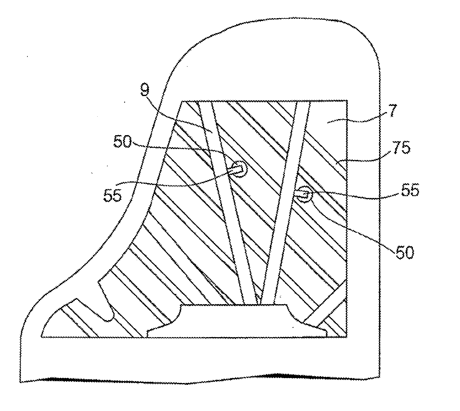
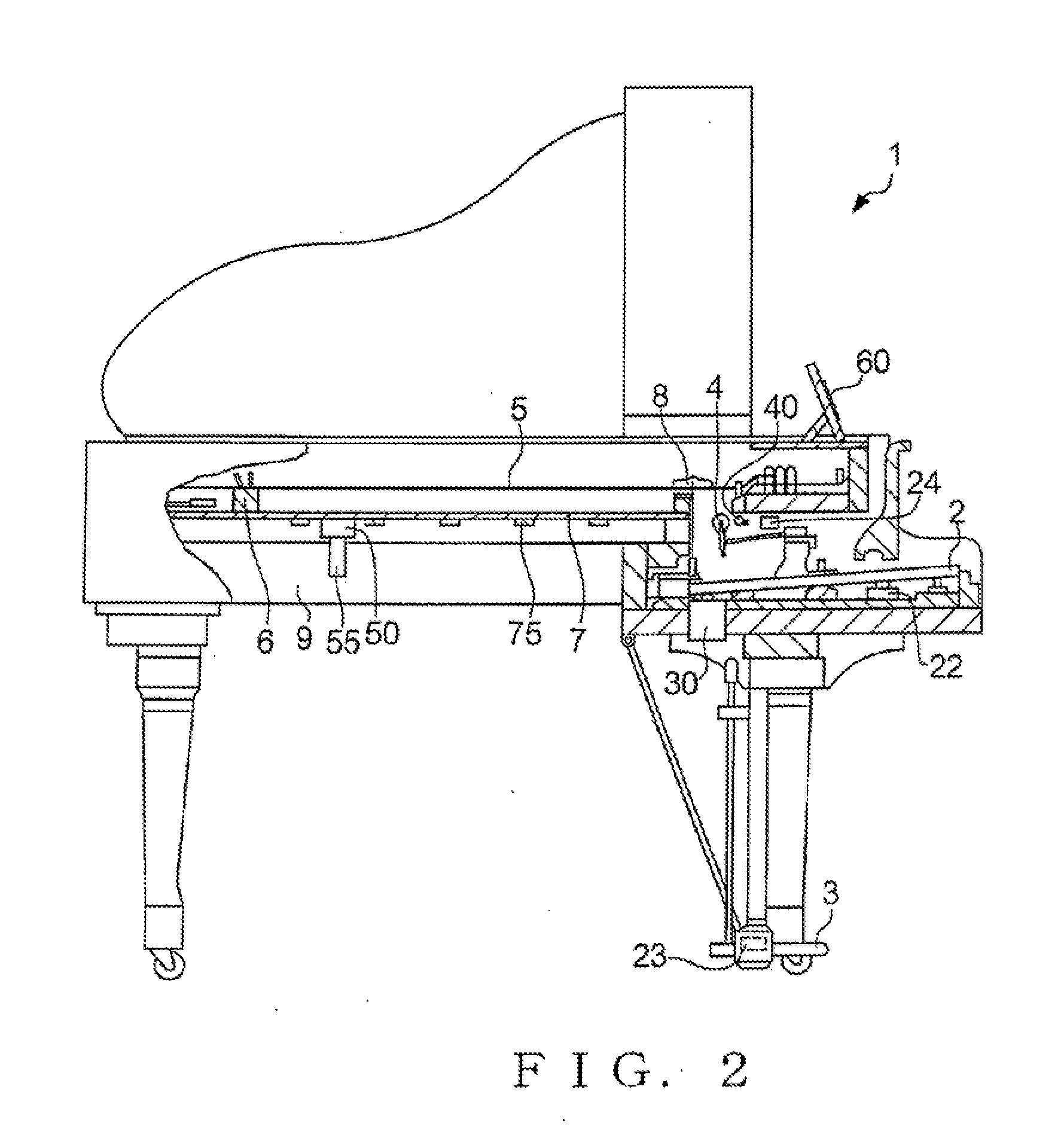
The present invention aims to impart a sound of an acoustic piano with an acoustic effect without compromising the natural feeling of the acoustic piano sound. It achieves this by generating vibration corresponding to a sine wave signal based on the fundamental frequency of the string struck by the hammer and transmitting it to the keys via a vibration transmission structure. The invention can adjust the amplitude of the sine wave signal for each string to control the acoustic effect for each hammer-struck string. Additionally, the invention includes a detection section, a signal generation section, a setting section, a vibration section, and a vibration transmission structure, which allow for precise control of the acoustic effect for each string.

Problems solved by technology

However, because the vibration signal to be used for driving the soundboard is merely a signal obtained by picking up the vibration of the string of the acoustic piano as-is, it comprises various frequency components, and thus, the technique disclosed in the relevant patent literature cannot perform free control, like control for driving the soundboard while emphasizing a particular harmonic component, so that it can achieve only poor control performance or controllability.
With the technique disclosed in the relevant patent literature, where such feedback vibration to the string contains various and complicated frequency components, an unintended sound generation state may sometimes result due to synthesis between the original string vibration and the feedback vibration depending on relationship between the original string vibration and the feedback vibration.

Method used


Image

  • Acoustic effect impartment apparatus, and piano
  • Acoustic effect impartment apparatus, and piano
  • Acoustic effect impartment apparatus, and piano

Examples


Embodiment Construction

Overall Construction

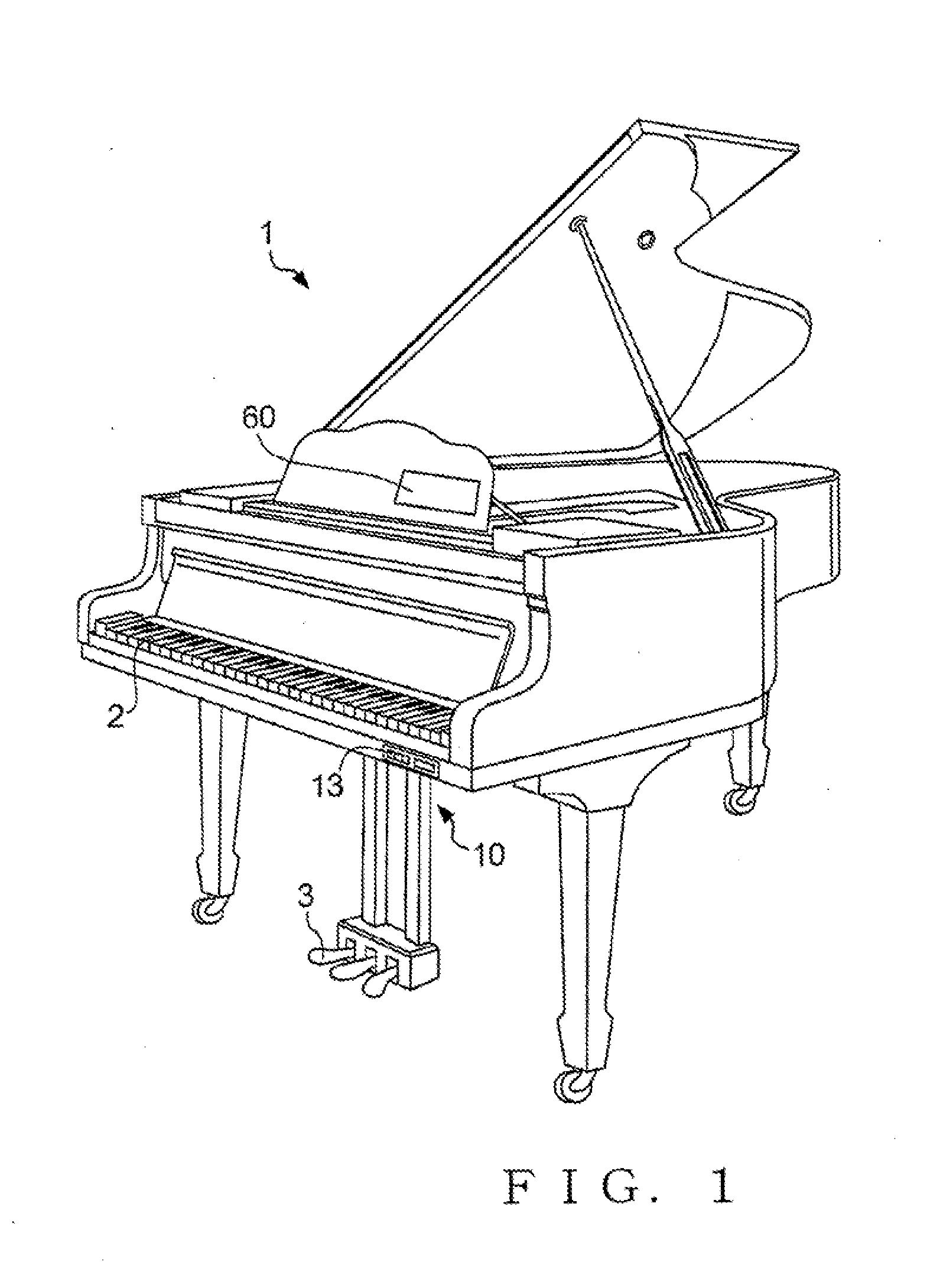
[0033]FIG. 1 is a perspective view showing an outer appearance of a grand piano 1 employing a preferred embodiment of an acoustic effect impartment apparatus of the present invention. The grand piano 1 includes a keyboard provided on a front side (i.e., a side closer to a human player or user playing the piano 1) of the piano 1 and having a plurality of keys 2 operable by the human player or user for a music performance, and pedals 3. The grand piano 1 also includes a tone generator device 10 having an operation panel 13 on its front surface portion, and a touch panel 60 provided on a portion of a music stand. User's instructions can be input to the tone generator device 10 by the user operating the operation panel 13 and touch panel 60.

[0034]The grand piano 1 is capable of generating a sound in any one of a plurality of sound generation modes that corresponds to a user's instruction. As in the conventionally-known grand pianos, the plurality of sound generation ...


PUM


Abstract

An acoustic effect impartment apparatus detects striking of any one of strings by a corresponding hammer in an acoustic piano like a grand piano, and vibrates a vibration section with a driving waveform signal obtained by synthesizing sine wave signals of the fundamental frequency and harmonic frequency of the hammer-struck string. Such vibration of the vibration section is transmitted to the keys via a soundboard and bridge of the piano. Thus, vibration is excited in the hammer-struck string by the striking with the hammer but also by the driving waveform signal, so that an acoustic effect corresponding to the driving waveform signal is imparted. Because the driving waveform signal is a simple signal using the sine wave signals corresponding to the fundamental frequency of the string, a natural feeling of the acoustic piano will not be lost even when the acoustic effect is imparted.

Description

BACKGROUND[0001]The present invention relates to techniques for changing or controlling a sound (i.e., musical sound or tone) of an acoustic piano.[0002]In the field of acoustic pianos, there have been developed control techniques for changing a sound generated by a keyboard performance on the piano. One example of such control techniques additionally uses an electronic sound generator that outputs an electronic audio signal, such as that of a desired musical instrument sound, in accordance with behavior of a key. In such a case, an electric sound etc. are generated from the electronic sound generator together with an acoustic sound generated from the acoustic piano, or without such an acoustic sound (i.e., with the acoustic piano kept in a silent state). However, with the control technique where an electric sound generated from the electronic sound generator is directly inserted as noted above, a natural feeling of sound generation by the acoustic piano sometimes cannot be reproduc...

Claims


Application Information

Patent Timeline
Patent Type & Authority Applications(United States)
IPC IPC(8): G10C3/06
CPCG10H1/0091G10H2230/011G10H3/26G10F1/02G10H3/22G10K9/13
Inventor KOSEKI, SHINYAOKUYAMA, FUKUTARO
Owner YAMAHA CORP
Learn More