Conveyor roll with centrifugal force-operated magnetic brake

a technology of centrifugal force and magnetic brake, which is applied in the direction of conveyors, conveyor parts, storage devices, etc., can solve the problems of particularly long service life of hypersteresis brakes, and achieve the effect of sufficient braking for

Active Publication Date: 2013-04-11
INTERROLL HLDG
View PDF7 Cites 39 Cited by
  • Summary
  • Abstract
  • Description
  • Claims
  • Application Information

AI Technical Summary

Benefits of technology

[0018]Developing the claimed conveyor roller, one found that the use of conventional eddy-current brakes can be disadvantageous if a braking effect is created by the eddy-current brake already in the lower speed range, since thereby the start of particularly lightweight goods to be conveyed on conveyor paths with a particularly flat inclination can be influenced negatively. By means of the claimed construction, in which the magnetic component and the braking component can be brought into a rest position relative to each other, the braking effect of the eddy-current brake can be reduced to almost zero, so that the starting torque of the retarded conveyor rollers can be reduced. Thus, it is possible to increase the weight area of goods transportable on a conveyor path with such conveyor rollers.
[0058]A further embodiment relates to one of the above-described conveyor rollers, wherein one of the centrifugal disks is connected with the brake drive. In this embodiment, the first centrifugal disk, which is connected with the brake drive, can have stops that restrict or prevent a movement of the centrifugal disk in a direction parallel to the axis of rotation of the covering element. The stops can be formed as finger-like projections, in particular integrally with the first centrifugal disk. Recesses can be provided on the second centrifugal disk, through which the finger-like projections project, so that the finger-like projections can be supported on an abutment on the other side of the second centrifugal disk. This configuration ensures that the braking function of the conveyor roller can be maintained even if the spring element, which is provided for biasing the two centrifugal disks, breaks.

Problems solved by technology

Hysteresis brakes are also characterized by a particularly long service life.

Method used


Image

  • Conveyor roll with centrifugal force-operated magnetic brake
  • Conveyor roll with centrifugal force-operated magnetic brake
  • Conveyor roll with centrifugal force-operated magnetic brake

Examples


Embodiment Construction

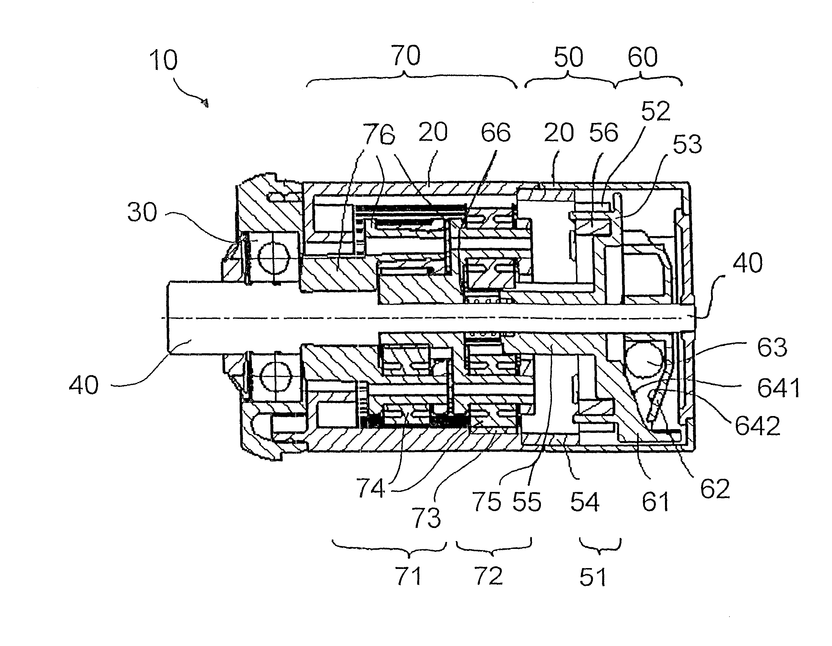
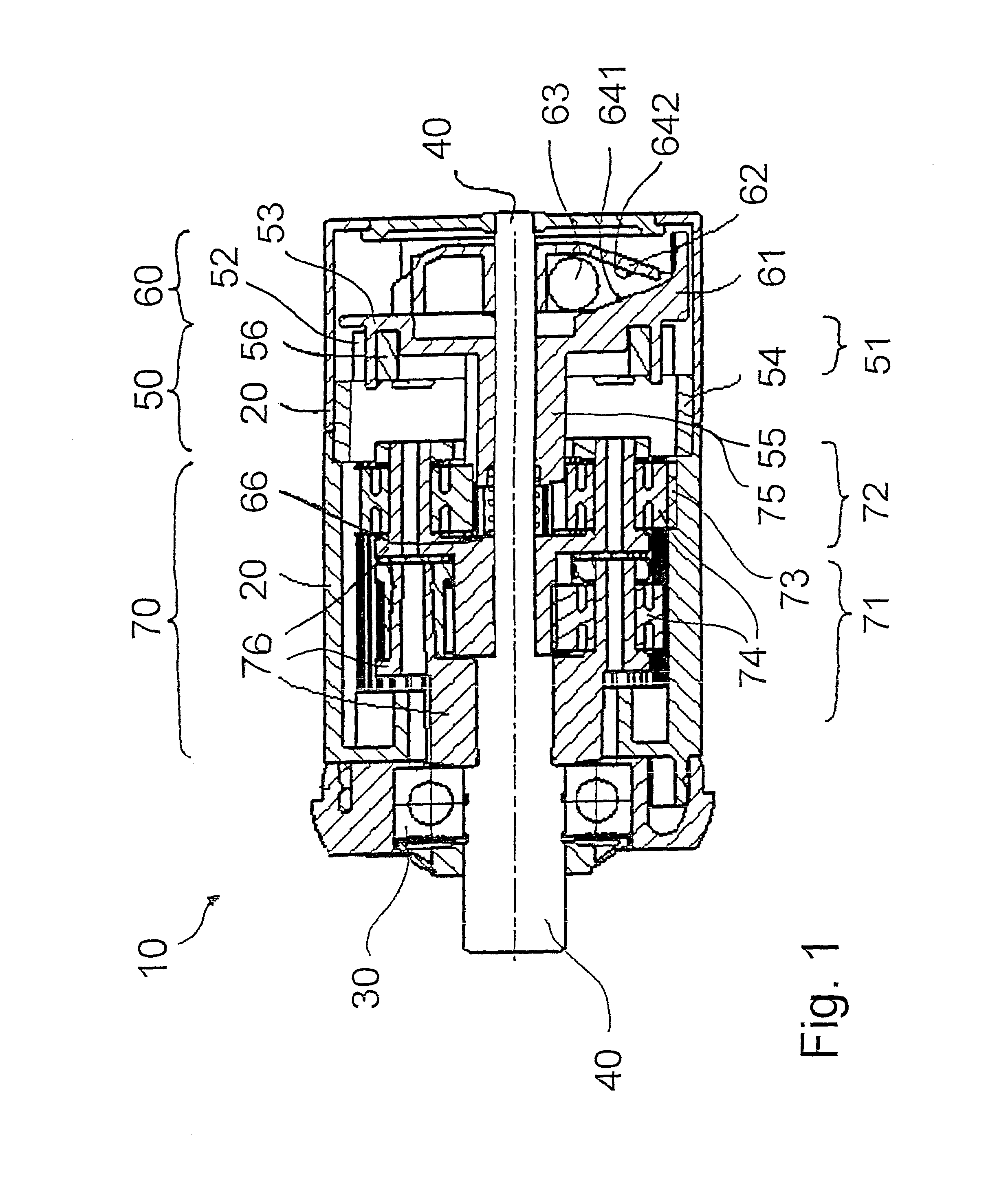
[0072]FIG. 1 shows an embodiment of a conveyor roller 10 with a covering element 20, which is supported on an axle via bearings 30, of which only one is shown. In the illustrated embodiment, the axle is configured in a two-part form, so that the conveyor roller 10 has an axle element 40, which in the conveyor roller 10 illustrated in FIG. 1 is arranged on the left side of the conveyor roller 10. Moreover, the conveyor roller 10 can have another axle element on the opposite side. A construction with a continuous axle is conceivable as well.

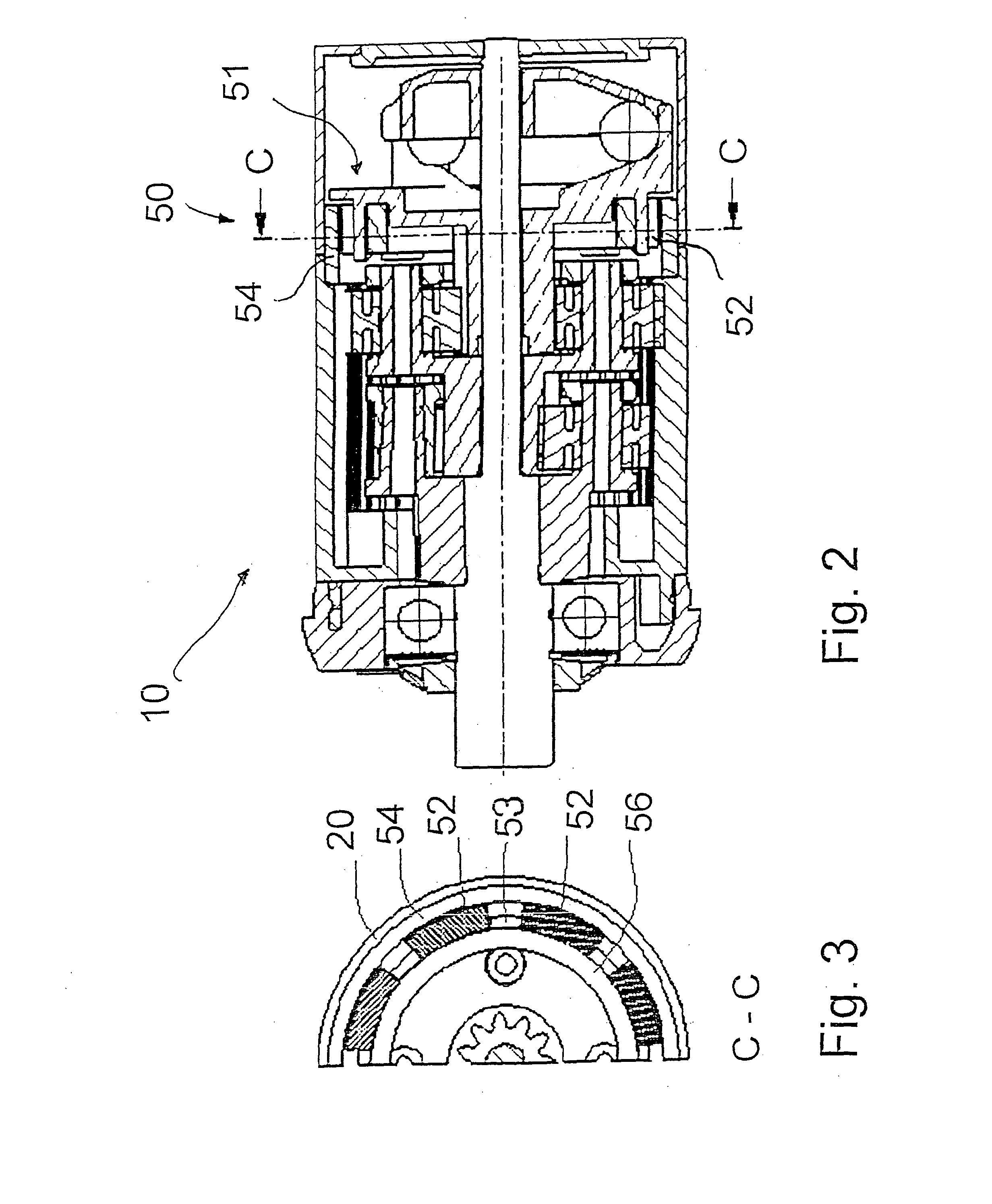
[0073]Within the covering element 20, the illustrated conveyor roller 10 has a gearing 70, a magnetic brake 50 configured as an eddy-current brake, and a centrifugal device 60.

[0074]The gearing 70 is configured as a two-stage planetary gearing with a first gearing stage 71 and a second gearing stage 72. Each of the gearing stages 71, 72 has a planet carrier 76 with three planetary gears 74 rotatably supported on the planet carrier 76, which are eng...


PUM


Abstract

A conveyor roller (10) has a cover (20), an axle (40), and a magnetic brake (50) having a magnetic component (51) and a braking component (54). The cover (20) is supported rotatably about an axis of rotation relative to the axle (40). The magnetic brake (50) is provided kinematically between the axle (40) and the cover (20) and is connected to the axle (40) and the cover (20) so that rotation of the cover (20) about the axis of rotation can be retarded by the magnetic brake (50). The magnetic component (51) and the braking component (54) are arranged displaceably relative to each other between a rest position and a braking position. A centrifugal device (60) for a rotational speed-dependent displacement of at least one of the magnetic brake components (51, 54) is provided between the rest position and the braking position.

Description

BACKGROUND OF THE INVENTION[0001]1. Field of the Invention[0002]The invention relates to a conveyor roller and to a conveyor path comprising such a conveyor roller.[0003]2. Description of the Related Art[0004]Roller conveyors with rollers exist in the prior art. These roller conveyors are used, for example, in rack storage systems, wherein a rack can have a plurality of roller conveyors arranged above and alongside one another. A plurality of pallets with goods can be mounted one behind the other on a roller conveyor, these pallets running on the rollers.[0005]The roller conveyors are generally loaded either from one side and unloaded from the other side, so that the goods that pass onto the roller conveyors first are also unloaded again first therefrom. These rack storage systems are called first-in / first-out storage systems or FIFO storage systems. Some of these FIFO roller conveyors have an inclination which slopes from the loading point to the unloading point, so that pallets lo...

Claims


Application Information

Patent Timeline
Patent Type & Authority Applications(United States)
IPC IPC(8): B65G13/075
CPCB65G13/075B65G1/08B65G17/24B65G23/08B65G47/261B65G47/266B65G47/8823B65G2205/04
Inventor SEJOURNE, JEROME
Owner INTERROLL HLDG
Why Eureka
Try Eureka