CSF shunt flow enhancer, method for generating CSF flow in shunts and assessment of partial and complete occlusion of CSF shunt systems

a shunt and enhancer technology, applied in the field of cerebrospinal fluid shunts, can solve the problems of progressive neurological dysfunction and death, shunt failure is still almost inevitable during a patient's life, and the need for shunt revision needs to be reasonably established

Active Publication Date: 2013-04-25
SHUNTCHECK +1
View PDF2 Cites 15 Cited by
  • Summary
  • Abstract
  • Description
  • Claims
  • Application Information

AI Technical Summary

Benefits of technology

[0036]FIG. 14 is a sectional view of micro-pumper with a force gauge and LED ligh

Problems solved by technology

Untreated hydrocephalus leads to progressive neurological dysfunction and death.
However, shunt failure is still almost inevitable during a patient's life.
However, since catheter replacement surgery carries risks of life-threatening complications such as infection or embolism, a need for shunt revision needs to be reasonably established.
The problem is that the usual clinical manifestations of shunt failure, such as headaches, vomiting, or loss of vision, are non specific and are difficult to differentiate from common, less serious illnesses, particularly in pediatric patients.
An unacceptably high number of hydrocephalic children still die as a result of shunt malfunction, primarily because of a failure to identify shunt blockage at an early stage [14].
The early diagnosis of shunt obstruction is complex and difficult.
While a number of shunt flow detection methods are available, none are diagnostic when used alone or are without complication, and there is little standardization to guide physicians in their interpretation (Table 1).
Physical examination of the patient, including pumping of the shunt reser

Method used


Image

  • CSF shunt flow enhancer, method for generating CSF flow in shunts and assessment of partial and complete occlusion of CSF shunt systems
  • CSF shunt flow enhancer, method for generating CSF flow in shunts and assessment of partial and complete occlusion of CSF shunt systems
  • CSF shunt flow enhancer, method for generating CSF flow in shunts and assessment of partial and complete occlusion of CSF shunt systems

Examples


Embodiment Construction

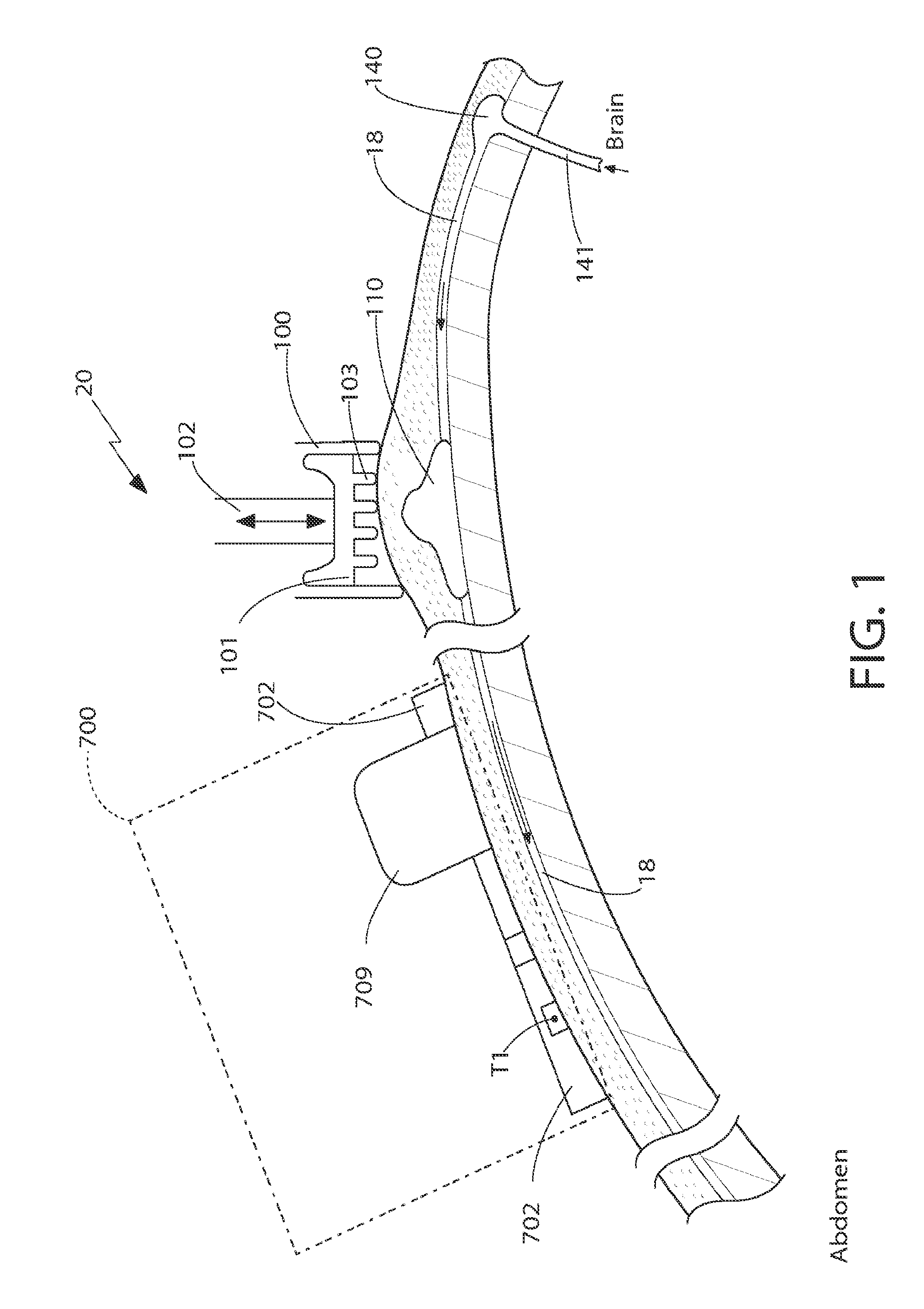
[0037]The invention of the present application is a micro-pumper 100 device that can be used as part of a cerebrospinal fluid (CSF) evaluation system 22 or it can be used as a stand-alone device for moving CSF. Thus, it should be understood that when used a part of a CSF evaluation system, the micro-pumper 100 is not limited to any one CSF evaluation system and that those CSF evaluation systems disclosed herein are by way of example only.

[0038]As will be discussed in detail later, the micro-pumper 100 generates pressure within the CSF in the CSF shunt which in turn causes flow of CSF. The micro-pumper 100 is able to generate a plurality of small pressure spikes (also referred to as “gentle vibrations”) in the CSF within the CSF shunt without creating large negative pressures (i.e., suction) at the CSF shunt tip, located within the brain of the patient. In particular, as shown in FIG. 1, the micro-pumper 100 is positioned against the skin over the dome portion of the CSF shunt valve....


PUM


Abstract

An apparatus capable of generating flow in cerebrospinal fluid (CSF) shunt systems by vibrating the shunt, tubing or shunt valve dome, or applying cyclical pressure to the various parts of the shunt system. A method of generating flow and method of using the apparatus in shunt patency assessment, for example, hydraulic resistance assessment, is also disclosed. The apparatus allows, in conjunction with a thermal dilution method or radionuclide method, a quick CSF shunt patency assessment based upon CSF shunt resistance and not upon CSF flow or intracranial pressure (ICP) separately. This provides a more objective measure of shunt obstruction compared to other methods. Furthermore, the apparatus can be used to enhance flow in shunts, identify partial occlusion before symptoms occur, differentiate between patent, partially-occluded and occluded shunts. The apparatus can be used to generate flow in shunts if there is a need to lower ICP or move drugs administered via an injection chamber or a shunt dome.

Description

CROSS-REFERENCE TO RELATED APPLICATIONS[0001]This PCT application claims the benefit under 35 U.S. C. §119(e) of Provisional Application Ser. No. 61 / 396,044 filed on May 21, 2010 entitled CSF SHUNT FLOW ENHANCER, METHOD FOR GENERATING CSF FLOW IN SHUNTS AND ASSESSMENT OF PARTIAL AND COMPLETE OCCLUSION OF CSF SHUNT SYSTEMS and under 35 U.S. C. §119(e) of Provisional Application Ser. No. 61 / 458,969 filed on Dec. 6, 2010 entitled SHUNT OCCLUSION DETECTION DEVICE and all of whose entire disclosures are incorporated by reference herein.BACKGROUND OF THE INVENTION[0002]1. Field of Invention[0003]This present invention generally relates to cerebrospinal fluid shunts and, more particular, to a device and method for testing for the presence, absence and / or rate of flow in the shunt tubing implanted under the skin.[0004]2. Description of Related Art[0005]The Surgical Management of Hydrocephalus[0006]Hydrocephalus is a condition of abnormal cerebrospinal fluid (CSF) homeostasis, resulting in a...

Claims


Application Information

Patent Timeline
IPC IPC(8): A61M27/00
CPCA61M27/006A61M27/002
Inventor SWOBODA, MAREKHOCHMAN, MATIAS GABRIELMATTIUCCI, MARK EVANFRITZ, FREDERICK J.
Owner SHUNTCHECK
Why Eureka
Try Eureka