Socket supported disco mirror ball

a disco mirror ball and socket support technology, applied in the field of new lighting devices, can solve problems such as damage to ceilings, and achieve the effect of slow rotation of the glob

Active Publication Date: 2013-05-02
OKANE MONA
View PDF7 Cites 24 Cited by
  • Summary
  • Abstract
  • Description
  • Claims
  • Application Information

AI Technical Summary

Benefits of technology

[0012]The present invention provides a mirror ball adapted to engage the socket of a ceiling mounted 120 VAC electric light fixture in order to be suspended and powered there from. A tubular stem having a proximal portion threaded in the manner of an Edison screw is provided extending downward from the fixture to a lower base. A lightweight mirrored sphere or globe having a void through its (vertical) polar axis is rotatably engaged on the stem and retained in place by the lower base which houses power systems, a controller and a motor engaged to an annular gear at the lower pole of the mirrored sphere in order to slowly rotate the globe. A power supply is used to reduce line voltage to 12v DC to drive the motor and operate one or more LED lighting elements directed at the mirrored surface and mounted at the ends of one or more arms radiating from the lower housing.

Problems solved by technology

Damage to a ceiling is a concern when a mirror bail is regularly hung and removed as is the ability of the ceiling to support whatever hook or screw the user might use.

Method used


Image

  • Socket supported disco mirror ball
  • Socket supported disco mirror ball
  • Socket supported disco mirror ball

Examples


Embodiment Construction

[0022]For the purposes of promoting an understanding of the principles of the invention, reference will now be made to the exemplary embodiment illustrated in the drawings and described below. The embodiment disclosed is not intended to be exhaustive or limit the invention to the precise form disclosed in the following detailed description. Rather, the embodiment is chosen and described so that others skilled in the art may utilize its teachings. It will be understood that no limitation of the scope of the invention is thereby intended. The invention includes any alterations and modifications in the illustrated device, the methods of operation, and further applications of the principles of the invention which would normally occur to one skilled in the art to which the invention relates.

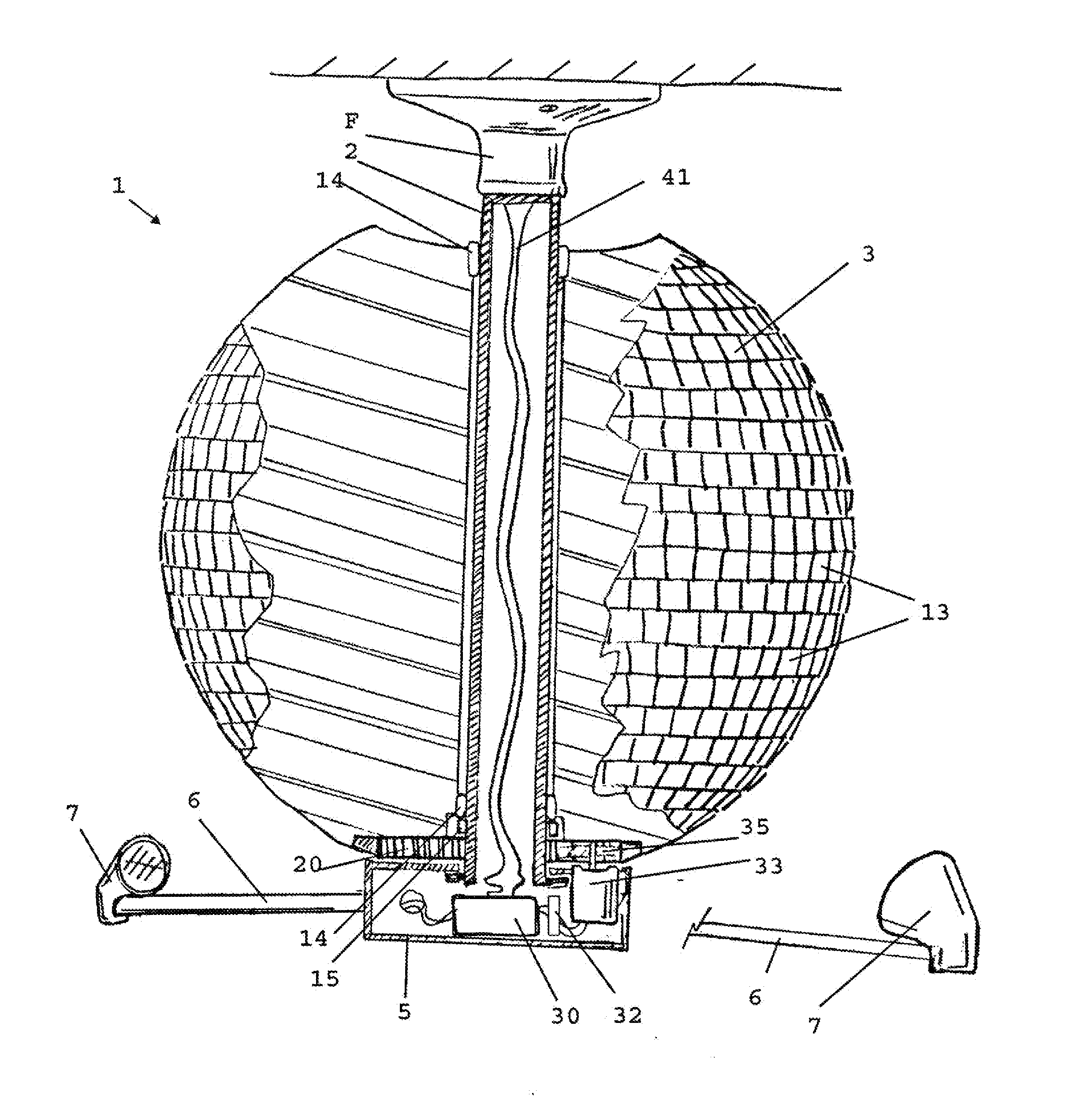
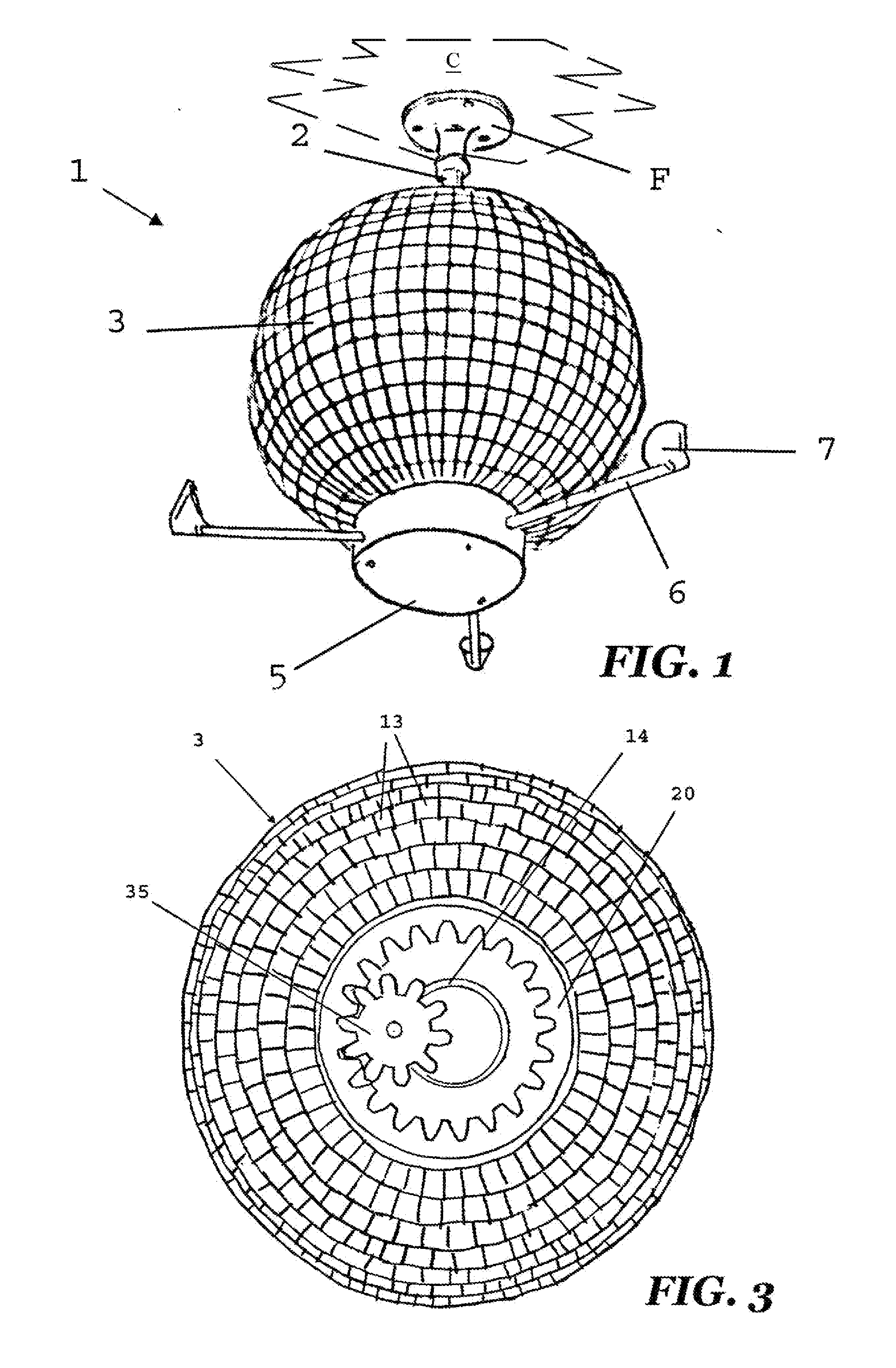
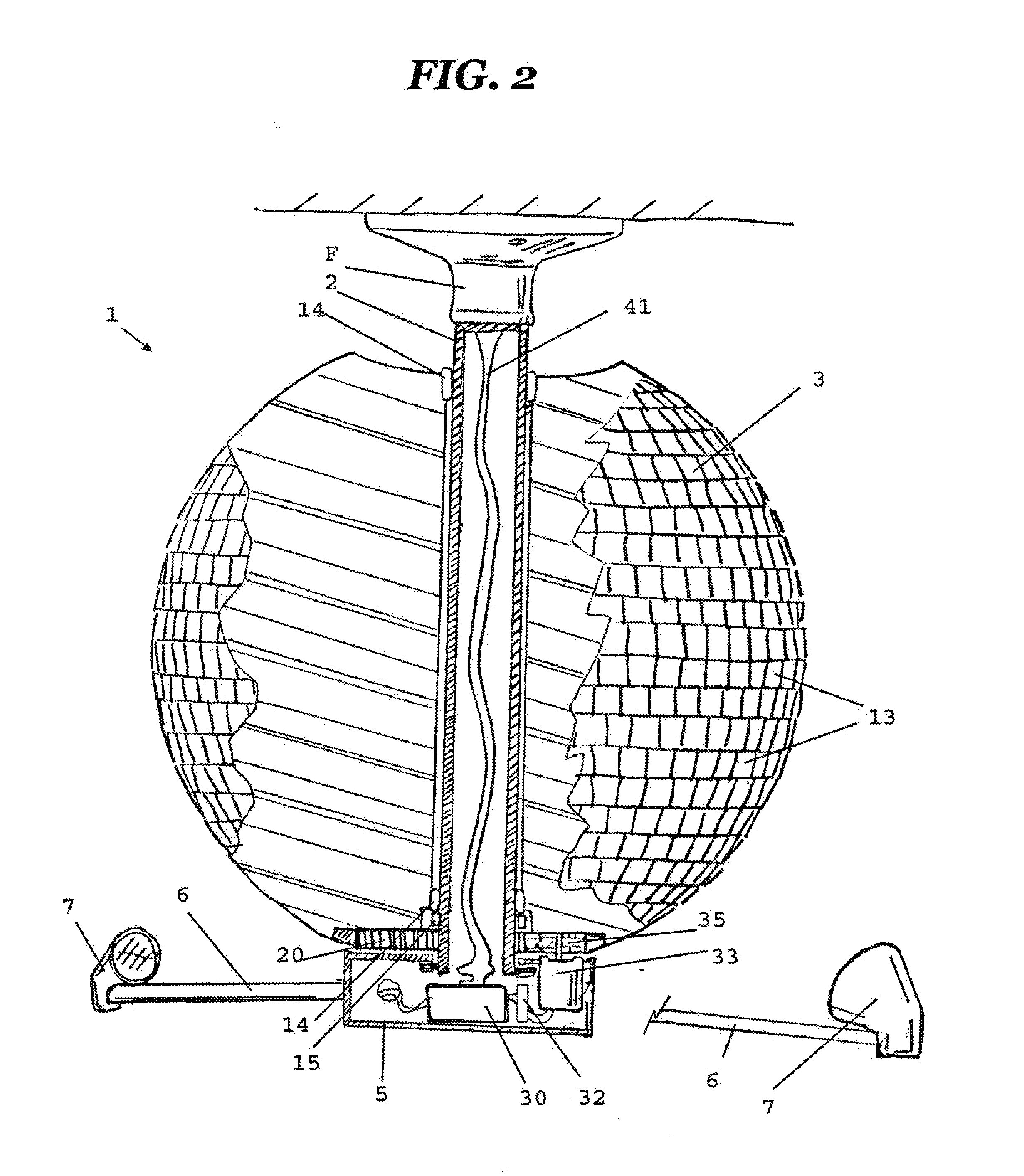
[0023]With reference to FIG. 1, a mirror ball 1 according to the present invention is affixed to a ceiling C by way engagement with an existing lighting fixture F. The mirror bail 1 engages the fixtur...


PUM


Abstract

A mirror ball adapted to engage the socket of a ceiling mounted electric light fixture in order to be suspended and powered therefrom. A tubular stem having a proximal portion threaded in the manner of an Edision screw is provided extending downward from the fixture to a lower base. A lightweight mirrored sphere or globe having a void through its (vertical) polar axis is rotatably engaged on the stem and retained in place by the lower base which houses power systems, a controller and a motor engaged to an annular gear at the lower pole of the mirrored sphere in order to slowly rotate the globe. A power supply is used to reduce line voltage to 12v DC to drive the motor and operate one or more LED lighting elements directed at the mirrored surface and mounted at the ends of one or more arms radiating from the lower housing.

Description

CROSS-REFERENCE TO RELATED APPLICATIONS[0001]The present application claims priority to U.S. provisional patent application Ser. No. 61 / 477,348 filed 20 Apr. 2011, which is also incorporated herein by reference.BACKGROUND OF THE INVENTION[0002]1. Field of the Invention[0003]The present invention relates to novelty lighting devices and more particularly to a lighting fixture suspended from an overhead bulb socket and having an internally motorized rotating mirror ball with stationery surrounding light sources to create a disco effect.[0004]2. Description of the Background[0005]The mirror ball is an iconic element of the “disco” era of the 1970's. Mirror balls were prominently featured over numerous dance floors at clubs such as Studio 54 in New York City as well as Brooklyn's fictional 2001 Odyssey, frequented by Tony Manero in 1977's Saturday Night Fever. The mirror ball's prominence in disco's led to it being popularly known as the disco ball although mirror balls date to at least ...

Claims


Application Information

Patent Timeline
Patent Type & Authority Applications(United States)
IPC IPC(8): F21V14/04
CPCF21V14/04G09F19/16F21S10/06
Inventor O'KANE, MONA
Owner OKANE MONA
Why Eureka
Try Eureka