Rotating electrical machine and manufacturing method thereof

Active Publication Date: 2006-07-13
HITACHI ASTEMO LTD
View PDF6 Cites 18 Cited by
  • Summary
  • Abstract
  • Description
  • Claims
  • Application Information

AI Technical Summary

Benefits of technology

[0012] The present invention provides for a rotating electrical machine wherein insulation resistivity of the coils as to voltage can be improved without changing the specifications of the coils.
[0027] Moreover, according to the present invention, a rotating electrical machine can be provided for wherein anti-inverter-surge properties are excellent, without introducing insulating sheets between unit coil end portions of unit coils, since voltage occurring at the contact portions between coil ends of unit coils of the same phase can be reduced.

Problems solved by technology

However, with conventional low-voltage rotating electrical machines below 1 kVrms, measures for dealing with voltage balance between coils with regard to steep surge voltage from inverter devices described above had not been taken.
This is thought to be due to the fact that generally, the probability of a lighting surge or on / off surge directly entering a low-voltage rotating electrical machine is low, and also that controlling the distributed capacitance between coils and the to-ground distributed capacitance of each of the parts of the coils using rectangular conductors as with high-voltage rotating electrical machines is difficult since low-voltage rotating electrical machines use stator coils made using round wire with enamel coating.
Another conceivable reason is that in the event of winding multiple coils at once without cutting the magnet wire, connecting capacitors for adjusting capacitance distribution between coils is difficult.
Consequently, there is the problem that the size of the rotating electrical machine increases.
Consequently, the problem of increased size of the rotating electrical machine arises.
Thus, either means have the problem that the rotating electrical machine increases in size due to the change in coil specifications.

Method used


Image

  • Rotating electrical machine and manufacturing method thereof
  • Rotating electrical machine and manufacturing method thereof
  • Rotating electrical machine and manufacturing method thereof

Examples


first embodiment

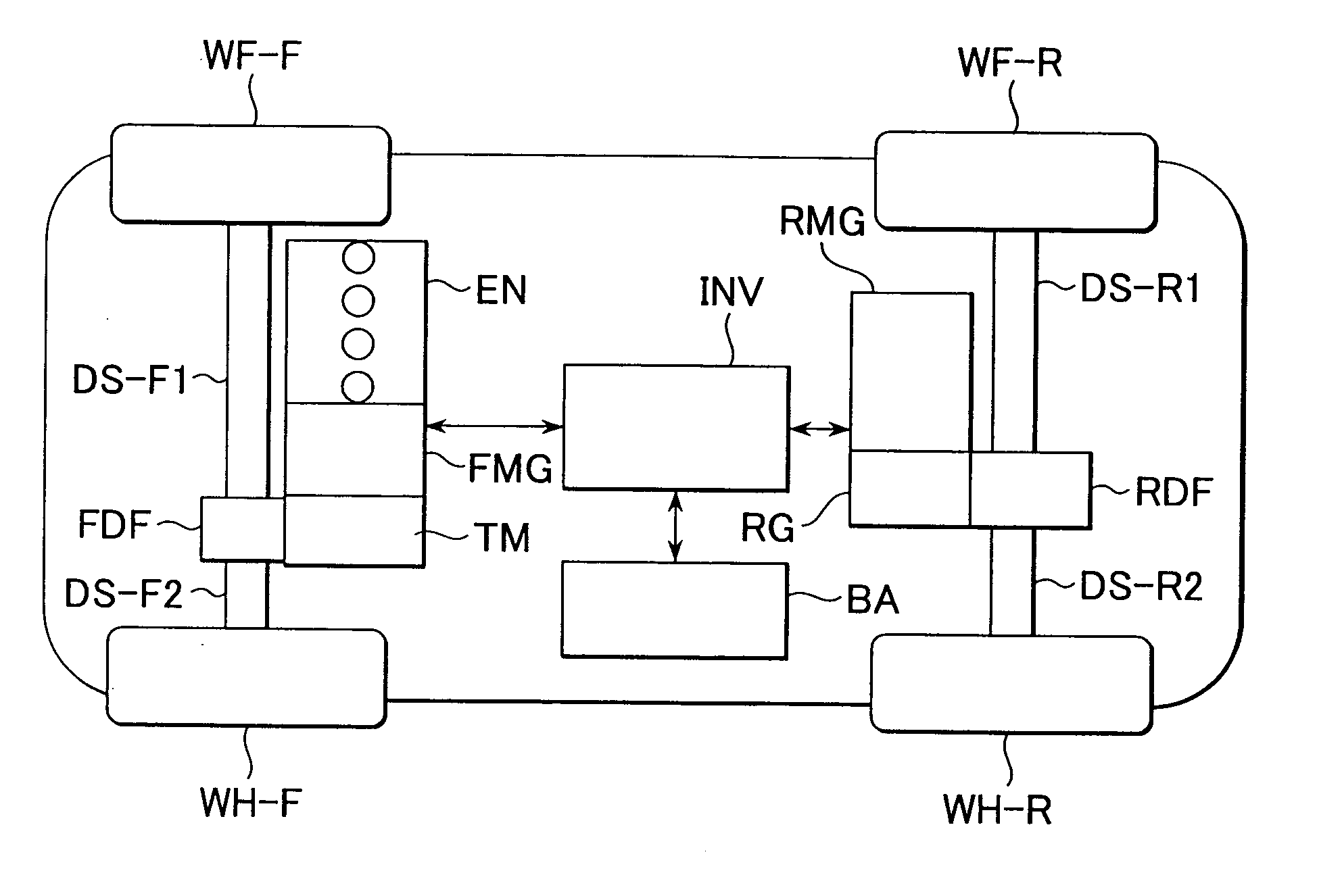
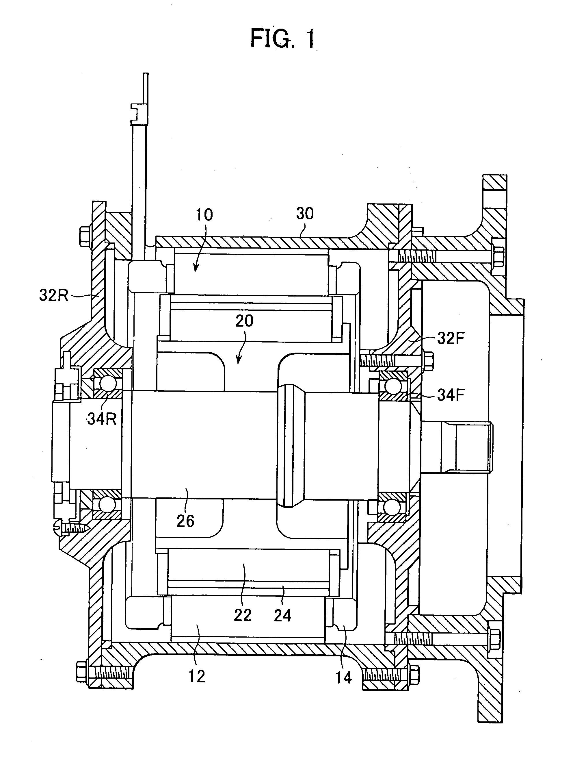
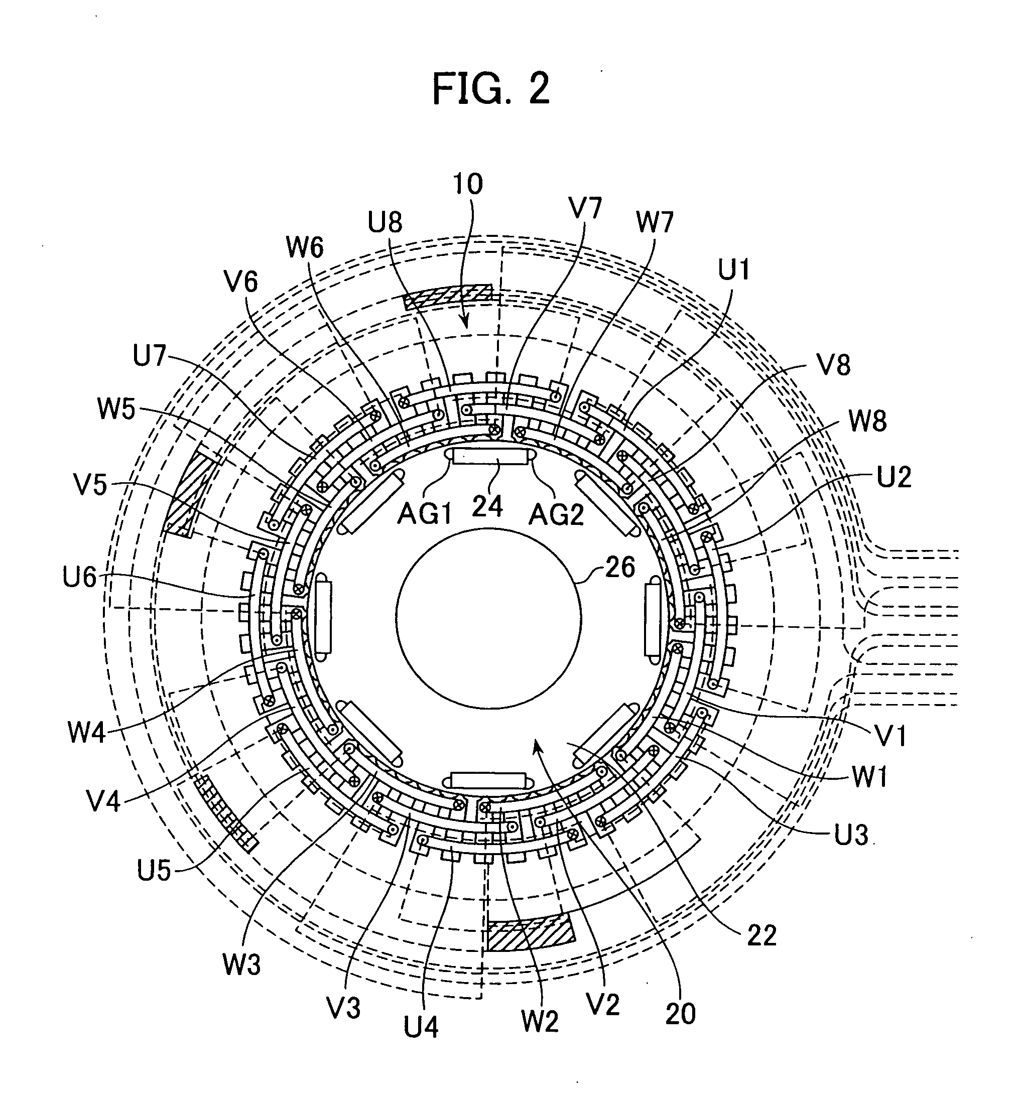
[0072] First, the configuration of a rotating electric machine according to a first embodiment will be described with reference to FIGS. 1 and 2. The first embodiment will be described regarding an example of a synchronous machine having a rotor with permanent magnets built in, with eight magnetic poles and 48 stator slots, distributed winding having been employed for winding the stator coil. This rotating electric machine is mounted in a hybrid automobile to serve as an automobile-driving rotating electric machine making up the driving source thereof along with an internal combustion engine. The rotating electric machine is driven by an inverter device which converts DC electrical power supplied from a battery, which is the electrical power source of the automobile, into AC electrical power.

[0073] With electrically-driven vehicles such as hybrid automobiles or the like, synchronous machines which have a rotor with permanent magnets built in and which are driven by an inverter devi...

second embodiment

[0120] Next, the configuration of a rotating electrical machine according to a second embodiment will be described with reference to FIGS. 13A through 15. Note that the overall configuration of the rotating electrical machine according to the second embodiment is the same as that shown in FIGS. 1 and 2.

[0121]FIGS. 13A through 13C are explanatory diagrams of a winding method for a stator coil in the rotating electrical machine according to the second embodiment, FIG. 14 is a placement diagram of winding wire wound on the stator coil in the rotating electrical machine according to the second embodiment, and FIG. 15 is an explanatory diagram of capacitance at the stator coil in the rotating electrical machine according to the second embodiment.

[0122] As with the case of the arrangement described with reference to FIGS. 8A through 9 and FIGS. 11A and 11B, the second embodiment will be described with the number of winds of a stator coil, the stator coil U1 for example, being 12T.

[0123...

third embodiment

[0136] Next, the configuration of a rotating electrical machine according to a third embodiment will be described with reference to FIG. 16. Note that the overall configuration of the rotating electrical machine according to the second embodiment is the same as that shown in FIGS. 1 and 2. FIG. 16 is a placement diagram of winding wire wound on the stator coil in the rotating electrical machine according to the third embodiment.

[0137] As with the case of the arrangement described with reference to FIGS. 8A through 9 and FIGS. 11A and 11B, the third embodiment will be described with the number of winds of a stator coil, the stator coil U1 for example, being 12T. With the third embodiment, the winding of one stator coil is divided into four winding groups, following which a predetermined number of turns are sequentially wound on a spool VL, using an automatic winder (four divided windings equal two reciprocal windings). That is to say, with the third embodiment, in the event that the...


PUM


Abstract

A stator coil is configured of a first group of six turns of conductive wire, and a second group also of six turns, with the first group of six turns being wound on a spool, leaving a gap the same as the diameter of the conductive wire between winds. Upon completion of winding the first group, the winding is turned back, and the second group of six turns is wound in the gap, so as to be adjacent to the turns of the first group. The article is then inserted into a slot in a stator core of a stator, thereby configuring a stator coil. This provides for a rotating electrical machine and manufacturing method thereof with improved insulation resistivity regarding inverter surge voltage, and moreover high output can be obtained with a machine of comparable external dimensions with conventional machines.

Description

CROSS-REFERENCE TO RELATED APPLICATIONS [0001] This application is a Continuation-In-Part of U.S. application Ser. No. 11 / 259,032, filed Oct. 27, 2005, and claims the priority of Japanese Application No. 2005-101382, filed Mar. 31, 2005; Japanese Application No. 2004-315710, filed Oct. 29, 2004; and Japanese Application No. 2005-177117, filed Jun. 17, 2005, which are hereby incorporated by reference.BACKGROUND OF THE INVENTION [0002] 1. Field of the Invention [0003] The present invention relates to a rotating electrical machine and a manufacturing method thereof. [0004] 2. Description of the Related Art [0005] In recent years, operating rotating electrical machines at variable speeds using an inverter device has become widespread, from the perspective of energy conservation. However, it has been reported that in the event of driving a rotating electrical machine using an inverter device, voltage higher than when driving with conventional commercial frequency power is generated betwe...

Claims


Application Information

Patent Timeline
IPC IPC(8): H02P1/24H02P1/42H02P23/00
CPCH02K3/28
Inventor YASUHARA, TAKASHIKOIZUMI, TAKAYUKITAKEUCHI, RYOZOOBATA, KOJIKOBAYASHI, HIDEMITSU
Owner HITACHI ASTEMO LTD
Why Eureka
Try Eureka