Cavity filter with rotation adjustable loop

A cavity filter and loop technology, applied to waveguide devices, circuits, electrical components, etc., can solve the problems of difficult to obtain strong coupling, difficult cable assembly, inconvenient adjustment, etc., to achieve simple structure, convenient debugging, The effect of easy assembly

Active Publication Date: 2013-12-11
YANGZHOUSRKLE INDAL
View PDF10 Cites 19 Cited by
  • Summary
  • Abstract
  • Description
  • Claims
  • Application Information

AI Technical Summary

Problems solved by technology

This connection method makes cable assembly more difficult, and it is very inconvenient to adjust during the debugging process, and it is difficult to obtain strong coupling, so the effect is not ideal.

Method used


Image

  • Cavity filter with rotation adjustable loop
  • Cavity filter with rotation adjustable loop
  • Cavity filter with rotation adjustable loop

Examples


Embodiment Construction

[0022] Embodiments of the present invention will be described in further detail below in conjunction with the accompanying drawings.

[0023] Figure 1 to Figure 6 Shown is the structural representation of the present invention.

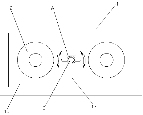
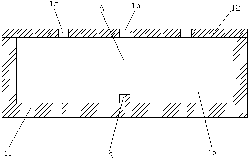
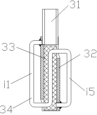
[0024] The reference signs are: coupling window A, adjustment gap S, first coupling section i1, second coupling section i5, metal cavity box 1, dielectric resonator 1a, coupling adjustment screw hole 1b, tuning screw hole 1c, metal Shell 11, metal cover plate 12, partition 13, TM dielectric resonator 2, TM dielectric resonator rod 21, tuning screw 22, tuning nut 23, negative coupling adjustable loop 3, connection opening 3a, coupling adjustment screw 31, metal tube 32 , Medium pipe 33, coupling cable 34, set nut 4.

[0025] Such as Figures 1 to 6 As shown, a cavity filter with a rotary adjustable circuit of the present invention includes a rectangular metal cavity box 1 whose inner cavity is divided by a partition wall 13 to form at least two die...


PUM


Abstract

The invention discloses a cavity filter with a rotation adjustable loop. The cavity filter comprises an internal cavity which is divided into a rectangular metal cavity box having at least two medium resonant cavities by a dividing wall. Each medium resonant cavity is provided with a TM medium resonator. The dividing wall is provided with a coupling window communicating with two adjacent medium resonant cavities. The coupling window is provided with a negative coupling adjustable loop which comprises a spiral adjusting part and a negative coupling loop with a coaxial transmission line structure. The spiral adjusting part penetrates through a coupling adjusting screw hole of the metal cavity box and extends out of the metal cavity box. The spiral adjusting part rotates and adjusts the negative coupling loop and distance between the TM medium resonators in the two adjacent medium resonant cavities so that a coupling value is changed. An adjusting gap is arranged between the bottom end surface of the negative coupling loop and the bottom wall of the coupling window. PpA problems that limited negative coupling and coupling intensity in conventional cavity filter assembling are different to adjust is effective solved. Besides, the cavity filter with the rotation adjustable loop has characteristics of being simple in structure, easy to assemble and convenient to debug.

Description

technical field [0001] The invention relates to the technical field of the wireless communication industry, in particular to the application technology of a radio frequency cavity filter using a TM dielectric resonator, in particular to a cavity filter with a rotation adjustable loop. Background technique [0002] At present, the development of wireless communication technology has put forward higher and higher requirements for mobile communication systems, and filters made of traditional metal materials can no longer meet the new technical requirements. Some new materials have replaced traditional metal materials in cavity filters. Dielectric resonators use some outstanding characteristics of dielectric ceramic materials to replace traditional metal material resonators. Dielectric ceramic materials have the characteristics of low loss, high dielectric constant, small frequency temperature coefficient and thermal expansion coefficient, and can withstand high power. Therefor...

Claims


Application Information

Patent Timeline
Patent Type & Authority Applications(China)
IPC IPC(8): H01P1/207H01P1/208
Inventor 马丁·卡弘张剑徐侦特
Owner YANGZHOUSRKLE INDAL
Why Eureka
Try Eureka