Reflow soldering system

a soldering system and reflow technology, applied in the direction of soldering apparatus, manufacturing tools,auxillary welding devices, etc., can solve the problems of microballs formed around the soldered part or the deviation of the electronic device position, forced heating time to become longer, and large facilities, etc., to achieve the effect of improving the efficiency of fume recovery

Active Publication Date: 2013-05-16
DENSO CORP
View PDF4 Cites 22 Cited by
  • Summary
  • Abstract
  • Description
  • Claims
  • Application Information

AI Technical Summary

Benefits of technology

[0014]The aspect of the invention of claim 7 comprises the aspect of the invention of claim 1 which has a hot air circulation system which makes hot air which is supplied from the hot gas blowing heating unit circulate to a preheating chamber, then has a fume recovery box cool flux fumes which are produced at the heating oven to condense for recovery, then furthermo

Problems solved by technology

If soldering a printed circuit board by the conventional reflow soldering method, there were the problems that microballs were formed around the soldered part

Method used


Image

  • Reflow soldering system
  • Reflow soldering system
  • Reflow soldering system

Examples


Embodiment Construction

[0027]Below, referring to the drawings, embodiments of the present invention will be explained. In the embodiments, parts of the same configuration are assigned the same reference notations and explanations are omitted.

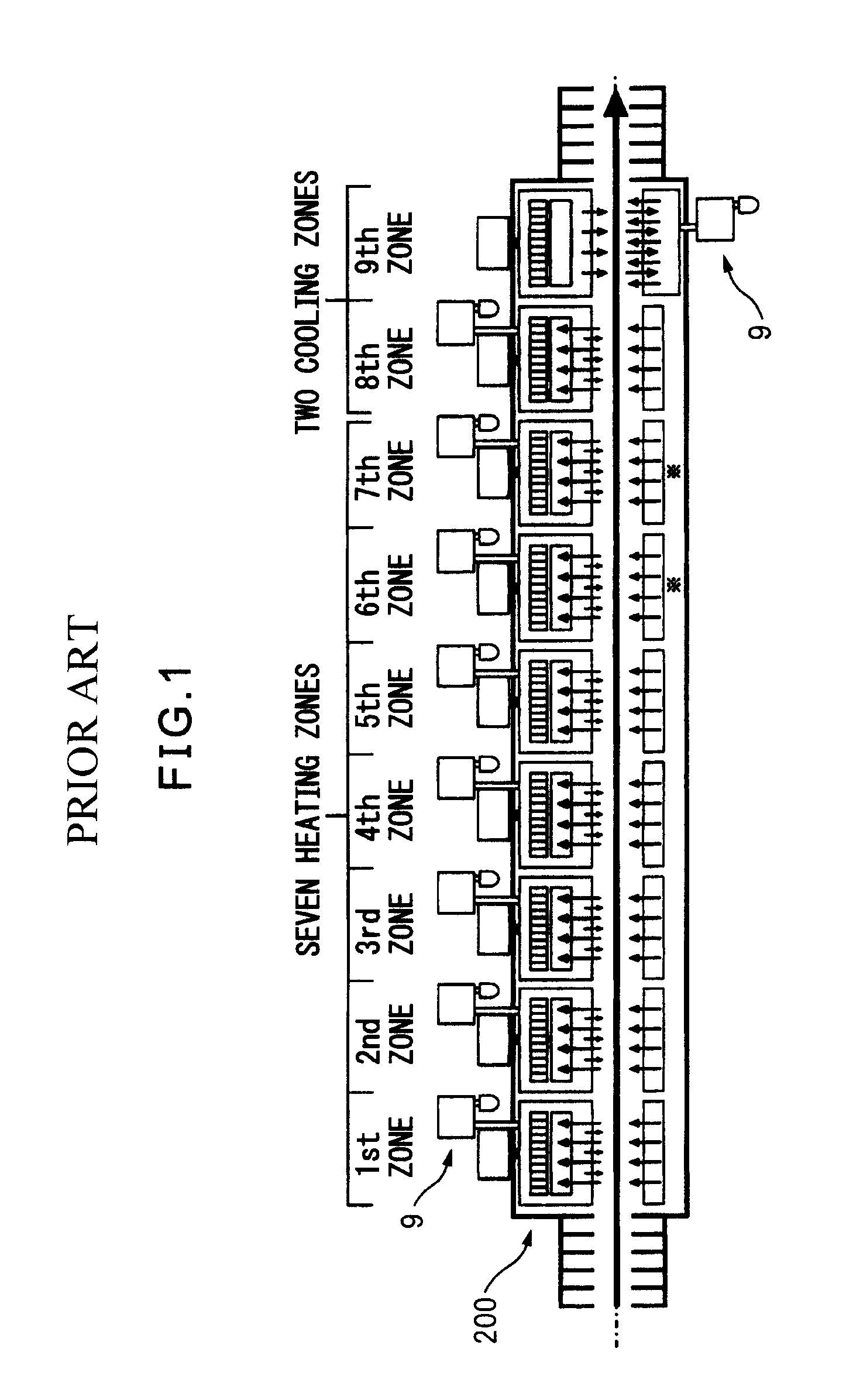
[0028]FIG. 1 is an explanatory view which explains a comparative art which forms a basis of the present invention. This comparative art is a hot air convection type reflow oven. This can handle a large number of types of products and enables uniform heating. However, in this comparative art, to enable uniform heating, the oven length has to be increased. The heating time ends up becoming longer and the facility ends up becoming larger in size. Further, in order to reduce the amount of use of nitrogen (N2), the hot air circulation method is employed, but the facility is large in size and the entry and exit parts for the material being heated are opened for conveyor transport, so the flow of hot air cannot be controlled and flux fumes spread and stick to the inside of t...


PUM

PropertyMeasurementUnit
Temperatureaaaaaaaaaa
Sizeaaaaaaaaaa

Abstract

A reflow soldering system wherein a heating oven is provided with a contact heating unit which has a transport rail and a top heat transfer heater, and with a hot gas blowing heating unit, the transport rail and top heat transfer heater are respectively provided with heaters which heat the outer edge part of the printed circuit board, and the transport rail or top heat transfer heater moves in an up-down direction so that the transport rail and top heat transfer heater clamp and heat the outer edge part of the printed circuit board.

Description

BACKGROUND OF THE INVENTION[0001]1. Field of the Invention[0002]The present invention relates to a reflow soldering system which solders a printed circuit board (PCB) wherein the system features both the high heat transfer rate of heating by contact heat transfer and the uniform heating of heating by blowing hot gas.[0003]2. Description of the Related Art[0004]In the conventional reflow soldering method of printed circuit boards, as shown in Japanese Unexamined Patent Publication No. 2004-304098, in particular FIG. 5, the practice has been to hold a printed circuit board for heating in a preheating zone of a reflow oven at a 100 to 200° C. preheating temperature, then rapidly raise the temperature to the peak temperature. If soldering a printed circuit board by the conventional reflow soldering method, there were the problems that microballs were formed around the soldered part or the electronic devices deviated in position from the soldered parts.[0005]In particular, to handle larg...

Claims


Application Information

Patent Timeline
IPC IPC(8): B23K3/04B23K3/08
CPCH05K3/3494B23K1/0016B23K1/008B23K3/08B23K3/00B23K3/04B23K2201/42B23K2101/42
Inventor SUKEKAWA, TAKUJIYAMADA, HIROYUKIINOMATA, NORIYASU
Owner DENSO CORP
Why Eureka
Try Eureka