Optical fiber cutting device and optical fiber cutting method

Active Publication Date: 2013-05-23
FUJIKURA LTD
View PDF11 Cites 1 Cited by
  • Summary
  • Abstract
  • Description
  • Claims
  • Application Information

AI Technical Summary

Benefits of technology

[0007]In many arts in the state of the art, to cut an optical fiber is done by pressing a cutting blade against the optical fiber. In accordance with studies by the present inventors, one of causes that lead a cut surface away f

Problems solved by technology

A cut surface should be, ideally, a plane surface perpendicular to the directi

Method used


Image

  • Optical fiber cutting device and optical fiber cutting method
  • Optical fiber cutting device and optical fiber cutting method
  • Optical fiber cutting device and optical fiber cutting method

Examples


Example

[0018]Exemplary embodiments of the present invention will be described hereinafter with reference to the appended drawings.

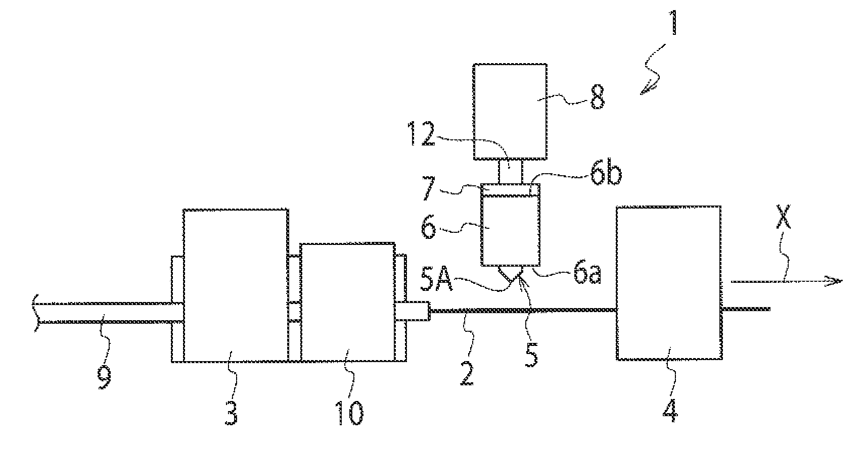
[0019]Referring to FIG. 1, an optical fiber cutting device 1 according to an embodiment of the present invention is comprised of gripping devices 3, 4 for gripping an optical fiber 2, a cutting blade 5, and a driving device 8 for driving the cutting blade 5 toward the optical fiber 2.

[0020]The first gripping device 3 and the second gripping device 4 are so disposed as to be apart from each other in a direction of an arrow X, and respectively grip the optical fiber 2 running in the direction of the arrow X. While a covering layer 9 may be frequently made to cover the optical fiber 2, a fiber holder 10 for holding the covering layer 9 is disposed close to the first gripping device 3. Thereby the fiber 2 is, at the side closer to the cutting blade 5 than the fiber holder 10, stripped of its covering layer 9 and is therefore placed in a naked condition.

[0021]The sec...


PUM

PropertyMeasurementUnit
Tensionaaaaaaaaaa
Resilienceaaaaaaaaaa

Abstract

A cutting device for cutting an optical fiber running in a first direction is comprised of a supporting piece having a free end and a fixed end and having resilience; a cutting blade supported by the supporting piece and so disposed as to come in contact with the optical fiber to make a right angle with the optical fiber at a point of the contact; and a driving device configured to press the supporting piece in a second direction in a plane perpendicular to the first direction, the second direction being not intersecting with the first direction.

Description

CROSS-REFERENCE TO RELATED APPLICATIONS[0001]This application is a Continuation Application of PCT International Application No. PCT / JP2011 / 078187 (filed Dec. 6, 2011), which is in turn based upon and claims the benefit of priority from Japanese Patent Application No. 2010-276848 (filed Dec. 13, 2010), the entire contents of which are incorporated herein by reference.BACKGROUND OF THE INVENTION[0002]1. Field of the Invention[0003]The present invention relates to an optical fiber cutting device and an optical fiber cutting method using the same.[0004]2. Description of the Related Art[0005]Broadband data communication services using optical fibers (FTTH) are rapidly and widely diffusing in recent years. As diffusion of FTTH progresses, the need for reduction of optical loss in optical fibers is growing. What should not be overlooked in optical loss is optical scattering at cut surfaces of terminal ends thereof. A cut surface should be, ideally, a plane surface perpendicular to the dir...

Claims


Application Information

Patent Timeline
IPC IPC(8): G02B6/25
CPCB26D1/45B26D7/14G02B6/25B26D5/16B26D5/08B26D5/086B26D5/12B26D1/455Y10T83/0405Y10T83/8717
Inventor KUROSAKA, YUYAIWAMATSU, MAKOTOTABATA, MANABU
Owner FUJIKURA LTD
Why Eureka
Try Eureka