Roll blade coating method and roll blade coating apparatus

Active Publication Date: 2013-05-23
RICOH KK
5 Cites 6 Cited by

AI-Extracted Technical Summary

Problems solved by technology

However, in the roll blade coating apparatus described in PTL 1, pressing force of the web against the roll blade in the width direction cannot be adjusted by mechanical suppress strength, and since the roll blade itself cannot be pressed, the adhesion amount on the web in the width direction is hard to be effectively adjusted.
Ho...

Method used

[0052]The roll blade coating apparatus of the present invention is a roll blade coating apparatus using a method including transferring an excessive amount of a coating liquid onto a continuously running web (a base material made of a woven fabric or a nonwoven fabric), and adjusting the excessive amount of the coating liquid to a desired adhesion amount with a roll blade. The web runs at high speed to improve productivity. Thus, a roll blade coating apparatus 1 of the present invention includes a roll blade 11 for measuring a coating liquid, a holding member 14 for holding the roll blade 11, in a back surface of the roll blade 11 a plurality of air cylinders 16 for uniformly pressing the holding member 14 against a web 13, and a holder 23 for holding the air cylinders 16.
[0060]However, when a pressing force of the roll blade 11 against the web 13 increases at both ends, the air pressure of the air cylinder 16 with respect to the part where the pressing force increases can be adjusted by appropriately reducing pressure using the pressure regulator 19, to thereby adjust the pressing force. Thus, uniform adhesion amount in the width direction can be obtained.
[0069]Therefore, by setting the arrangement pitch Y to a value smaller than the sum of 20 mm and the outer diameter D of the air cylinder 16, preferably a value smaller than the sum of 10 mm and the outer diameter D of the air cylinder 16, a width of the part to be pressed by one of the air cylinders 16 becomes appropriate, and the pressing force in the width direction can be finely adjusted.
[0075]Moreover, the flat plate members 20 can minimize an area of the holding member 14 for the roll blade 11, to which area the air pressure cannot be applied by the air cylinder 16, thus the pressing force in the width direction can be more uniformly applied.
[0077]A part of the flat plate member 20, which part is brought into contact with the rod 21 of the air cylinder 16 is formed into a...

Benefits of technology

[0027]The present invention can solve the conventional various problems, and achieve the objects, and can provide a roll blade coating method and a roll blade coating apparatus, which can suppress variations in adhesion amount of a coating liquid constantly occurring on a...

Abstract

A roll blade coating method including transferring an excessive amount of a coating liquid onto a continuously running web, and adjusting the excessive amount of the coating liquid to a desired adhesion amount with a roll blade, wherein the roll blade is held by a holding member for holding the roll blade, wherein the holding member is pressed by a plurality of air cylinders each configured to press the holding member, wherein the air cylinders are arranged in a side of the holding member, which side is opposite to a side where the holding member holds the roll blade, and wherein the air cylinders can separately be adjusted in air pressure.

Application Domain

Pretreated surfacesApplied substance rearrangement +1

Technology Topic

Mechanical engineeringCoating

Image

  • Roll blade coating method and roll blade coating apparatus
  • Roll blade coating method and roll blade coating apparatus
  • Roll blade coating method and roll blade coating apparatus

Examples

  • Experimental program(4)

Example

Example 1
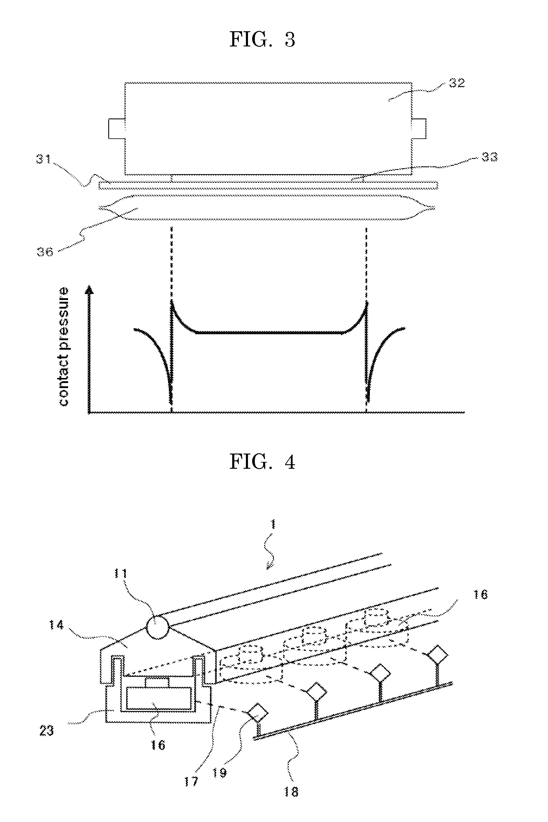
[0089]Using the roll blade coating apparatus of the present application shown in FIG. 4, coating was performed under the following conditions and while the adhesion amount of a coating liquid on a web in the width direction was confirmed using an on-line adhesion amount meter, the air pressure of each air cylinder was adjusted to minimize deviation in the adhesion amount thereof on the web in the width direction.
[0090]Specifically, as shown in FIG. 11, the pressures of four air cylinders 16 in the vicinity of each of the both ends of the web were reduced in 4 steps so as to be reduced in each step by 15% with respect to the average air pressure (100%) of the other 56 operating air cylinders. The air cylinders were arranged in such a manner that the edge of the web 13 was located substantially on the middle of the four air cylinders 16 in the width direction (X in FIG. 11).
[0091]Finally, the minimum deviation which could be adjusted was 3.6%. [0092] (1) Coating base (web): woodfree paper having a basis weight of 62 g/m2, a thickness of 70 μm, and a width of 1,560 mm [0093] (2) Coating liquid: 10% by mass of aqueous polyvinyl alcohol (PVA) solution [0094] (3) Coating rate: 400 m/min [0095] (4) Outer diameter of roll blade: 12 mm [0096] (5) Length of roll blade: 2,300 mm [0097] (6) Outer diameter of air cylinder: 20 mm [0098] (7) Arrangement pitch of cylinders: 26 mm [0099] (8) Number of arranged cylinder: 80 [0100] Number of operating cylinder: 64
[0101]The deviation in adhesion amount of the coating liquid on the web in the width direction was obtained by the following Equation (1).
Deviation in adhesion amount of a coating liquid in the width direction (%)={(maximum adhesion amount (g/m2)−minimum adhesion amount (g/m2)/average adhesion amount (g/m2))×100  Equation (1)

Example

Example 2
[0102]Using a roll blade coating apparatus of the present invention, in which a part of the disc-shaped flat plate member 20, which part is brought into contact with the rod 21 of the air cylinder 16 is formed into a downward-facing concave spherical surface, and a head of the rod 21 of the air cylinder 16 is formed into a convex spherical surface shown in FIGS. 7 and 8, coating was performed under the following conditions and while the adhesion amount of a coating liquid on a web in the width direction was confirmed using the on-line adhesion amount meter, the air pressure of each air cylinder was adjusted to minimize deviation in the adhesion amount thereof on the web in the width direction.
[0103]Specifically, as shown in FIG. 11, the pressures of four air cylinders 16 in the vicinity of each of the both ends of the web were reduced in 4 steps so as to be reduced in each step by 15% with respect to the average air pressure (100%) of the other 56 operating air cylinders. The air cylinders were arranged in such a manner that the edge of the web 13 was located substantially on the middle of the four air cylinders 16 in the width direction (X in FIG. 11).
[0104]Finally, the minimum deviation which could be adjusted was 3.1%. [0105] (1) Coating base (web): woodfree paper having a basis weight of 62 g/m2, a thickness of 70 μm, and a width of 1,560 mm [0106] (2) Coating liquid: 10% by mass of aqueous polyvinyl alcohol (PVA) solution [0107] (3) Coating rate: 400 m/min [0108] (4) Outer diameter of roll blade: 12 mm [0109] (5) Length of roll blade: 2,300 mm [0110] (6) Outer diameter of air cylinder: 20 mm [0111] (7) Arrangement pitch of cylinders: 26 mm [0112] (8) Number of arranged cylinder: 80 [0113] Number of operating cylinder: 64 [0114] (9) Diameter of disc: 25 mm

Example

Example 3
[0115]The deviation in adhesion amount of a coating liquid on a web in the width direction was minimized in the same manner as in Example 1, except that, as shown in FIG. 12, the pressures of two air cylinders 16 in the vicinity of each of the both ends of the web were reduced in 2 steps so as to be reduced in each step by 15% with respect to the average air pressure (100%) of the other 58 operating air cylinders. The air cylinders 16 were arranged in such a manner that the edge of the web 13 was located substantially on the middle of the two air cylinders 16 in the width direction (X in FIG. 12).
[0116]The number of arranged cylinder: 80
[0117]The number of operating cylinder: 62
[0118]Finally, the minimum deviation which could be adjusted was 3.9%.

PUM

PropertyMeasurementUnit
Diameter0.02m
Diameter0.01m
Diameter0.05m

Description & Claims & Application Information

We can also present the details of the Description, Claims and Application information to help users get a comprehensive understanding of the technical details of the patent, such as background art, summary of invention, brief description of drawings, description of embodiments, and other original content. On the other hand, users can also determine the specific scope of protection of the technology through the list of claims; as well as understand the changes in the life cycle of the technology with the presentation of the patent timeline. Login to view more.
Why Eureka
Try Eureka