
Handling mechanism

Inactive Publication Date: 2013-05-30
HONG FU JIN PRECISION IND (SHENZHEN) CO LTD +1
View PDF6 Cites 4 Cited by
  • Summary
  • Abstract
  • Description
  • Claims
  • Application Information

AI Technical Summary

Benefits of technology

The patent describes a handling mechanism used in manufacturing that can only slide in one direction. Additionally, the mechanism's clamping assembly can be easily distorted or destroyed due to heavy loads. The technical effect of this invention is the improvement of handling mechanisms in manufacturing by allowing for sliding in multiple directions and increased load capacity.

Problems solved by technology

In addition, a clamping assembly of the handling mechanism is easily distorted or even destroyed because of a heavy load being carried in one end thereof.

Method used


Image

  • Handling mechanism
  • Handling mechanism
  • Handling mechanism

Examples


Embodiment Construction

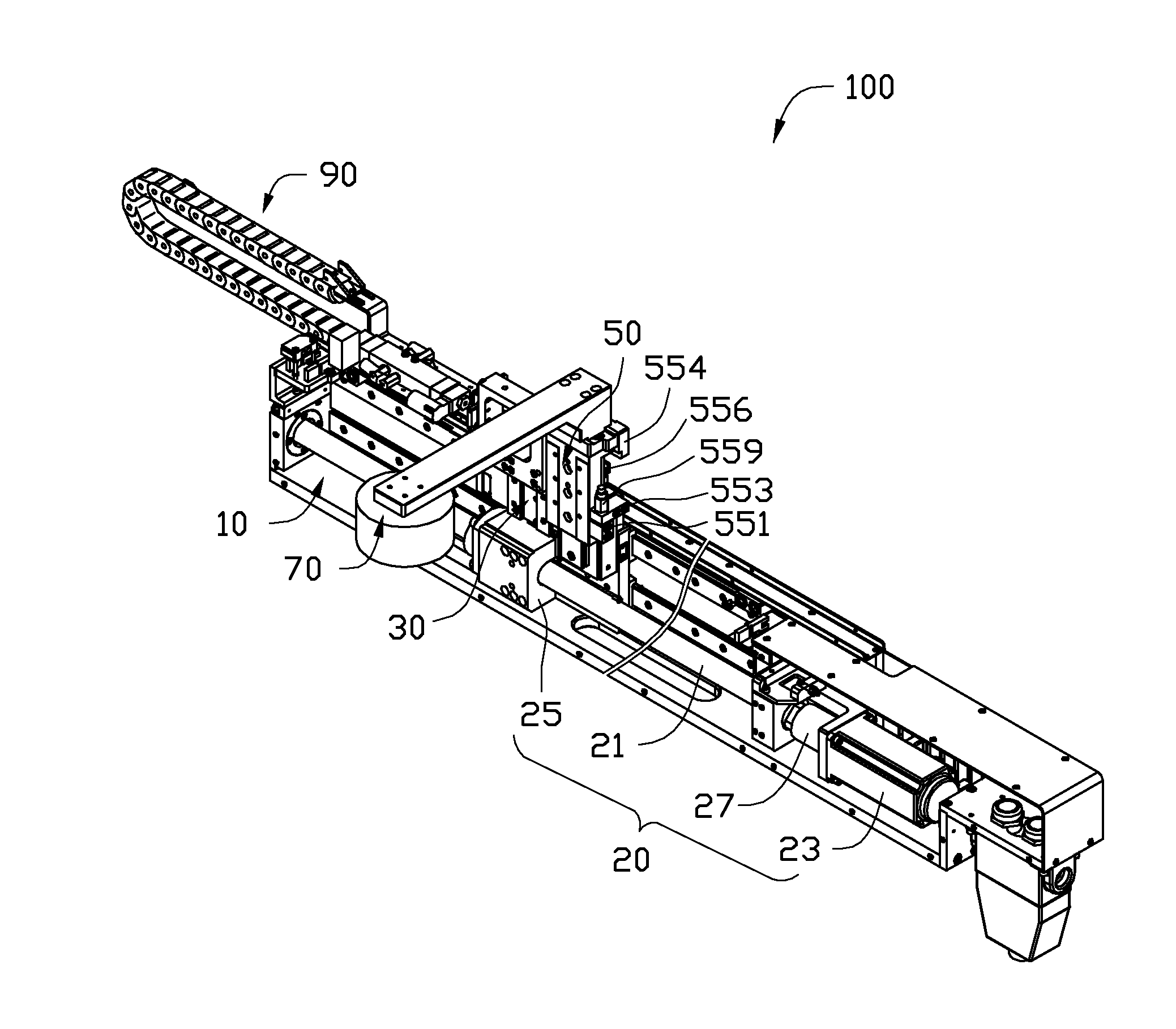
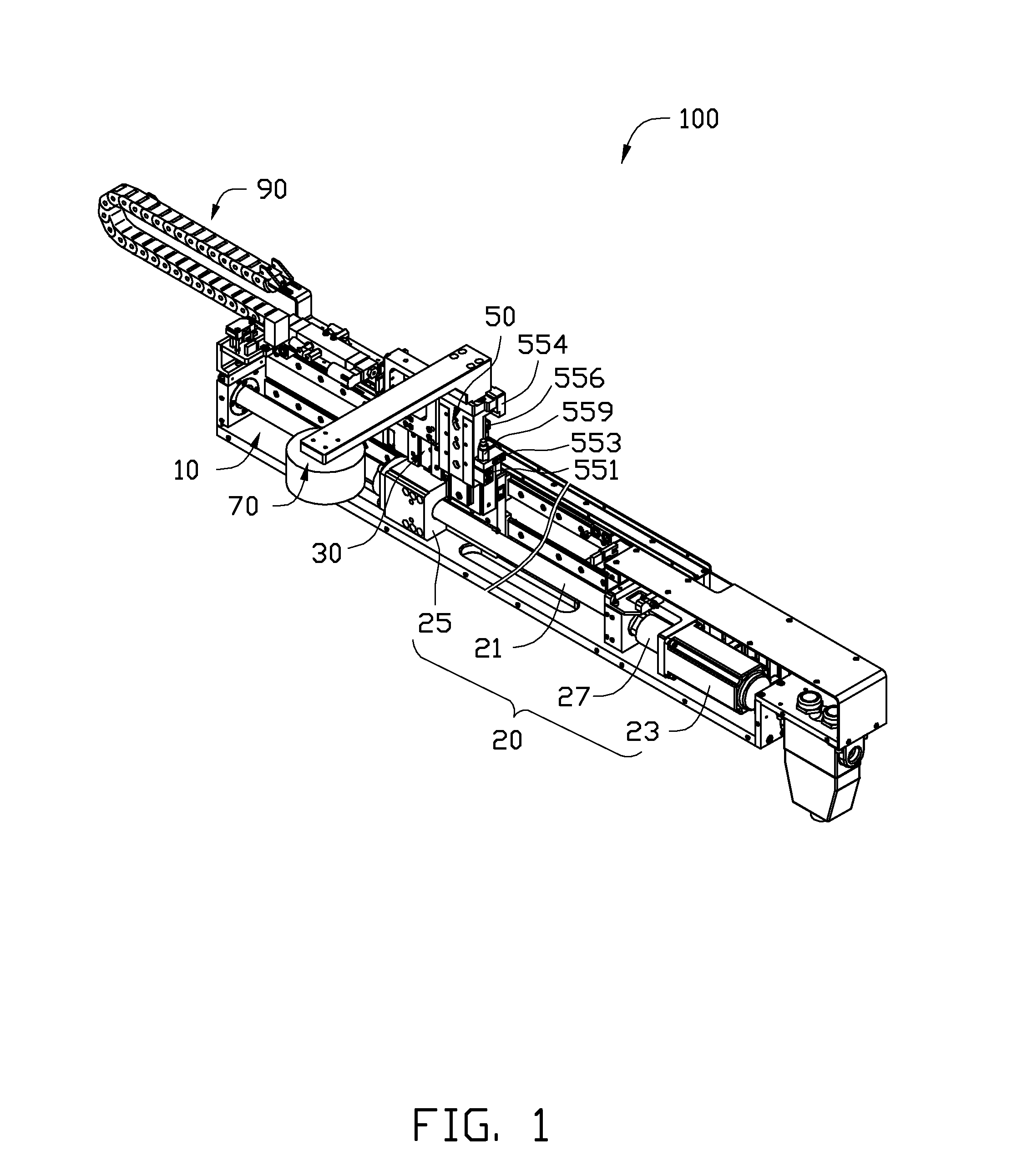
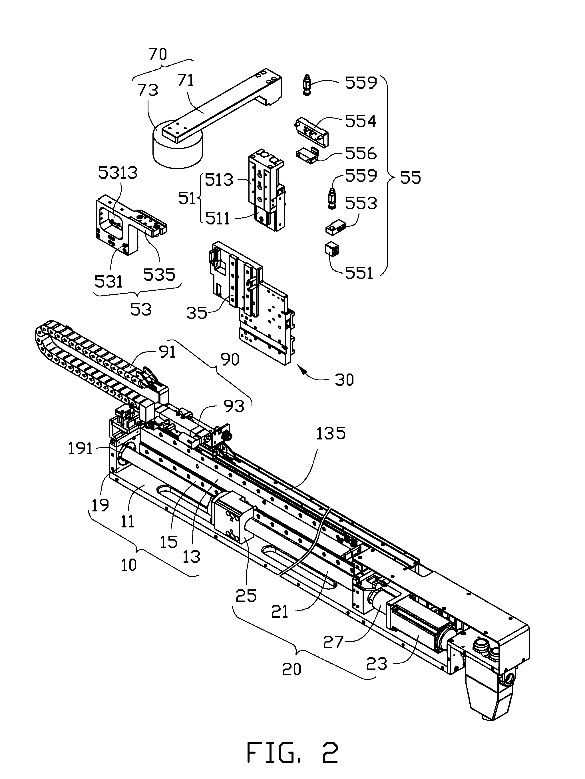
[0009]Referring to FIGS. 1 and 2, a handling mechanism 100 includes a mounting seat 10, a driving assembly 20, a sliding member 30, an extending assembly 50 assembled with the sliding member 30, and a clamping assembly 70. The driving assembly 20 is mounted on the mounting seat 10; the sliding member 30 is slidably mounted on the mounting seat 10 and driven by the driving assembly 20. The extending assembly 50 is installed on the sliding member 30 for supporting the clamping assembly 70. The clamping assembly 70 is fixed to the extending assembly 50 to clamp the workpieces (not shown).

[0010]The mounting seat 10 is a bar of material, including a bottom board 11, a supporting board 13 extending perpendicularly from one edge of the bottom board 11, and a pair of first guiding rails 15 fixed on the supporting board 13 along the longitudinal direction thereof. The pair of guiding rails 15 are parallel to and spaced from each other. The mounting seat 10 further includes two supporting bas...


PUM


Abstract

A handling mechanism comprises a mounting seat, a driving assembly, a sliding member, an extending mechanism and a clamping assembly. The driving assembly is mounted on the mounting seat. The sliding member is slidably mounted on the mounting seat and driven by the driving assembly. The extending mechanism comprises an extending member and a strength member. The extending member is positioned on the sliding member being capable of moving along a direction perpendicular to a direction of the movement of the mounting seat. The strength member is slidably positioned on the sliding member and connects with the extending member. The clamping assembly is fixed to the strength member for clamping very heavy workpieces.

Description

TECHNICAL FIELD[0001]The present disclosure relates to handling mechanisms, and more particularly, to a handling mechanism used for conveying workpieces.DESCRIPTION OF RELATED ART[0002]Handling mechanisms are used for conveying workpieces and materials during mechanical manufacturing. One handling mechanism includes a mounting seat, a driving assembly mounted on the mounting seat, and a sliding member driven by the driving assembly. However, the sliding member is merely capable of sliding relative to the mounting seat along one direction. In addition, a clamping assembly of the handling mechanism is easily distorted or even destroyed because of a heavy load being carried in one end thereof.[0003]Therefore, there is room for improvement in the art.BRIEF DESCRIPTION OF THE DRAWINGS[0004]The components in the drawings are not necessarily drawn to scale, the emphasis instead placed upon clearly illustrating the principles of the present disclosure. Moreover, in the drawings, like refere...

Claims


Application Information

Patent Timeline
IPC IPC(8): B65G47/90B65G25/06
CPCB23Q5/40
Inventor CHEN, WEN-SHENG
Owner HONG FU JIN PRECISION IND (SHENZHEN) CO LTD
Learn More