Image forming apparatus
a technology of forming apparatus and forming plate, which is applied in the direction of electrographic process apparatus, instruments, optics, etc., can solve the problems of envelopes suffering creases and inability to fix processing, and achieve the effect of preventing envelopes from suffering creases
- Summary
- Abstract
- Description
- Claims
- Application Information
AI Technical Summary
Benefits of technology
Problems solved by technology
Method used
Image
Examples
first embodiment
1.
Configuration Example of Image Forming Apparatus
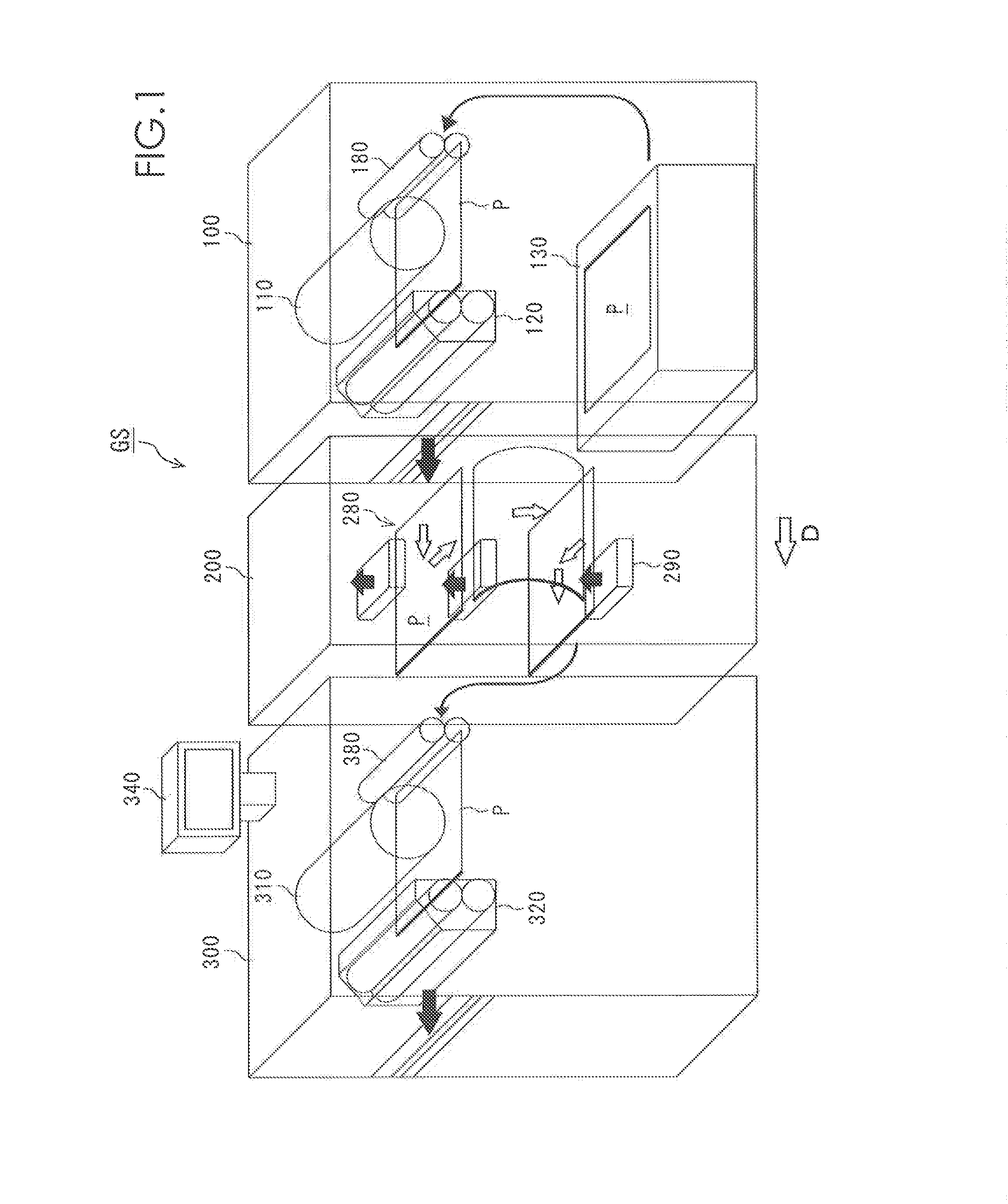
[0028]FIG. 1 shows a configuration example of an image forming apparatus GS according to a first embodiment of this invention. If is to be noted that dimensions and / or ratios in the drawings are exaggerated for convenience of explanation and they may be different from actual ones. The following will describe a case where images such as letters are formed on both surfaces of an envelope P as an example of a sheet of paper.
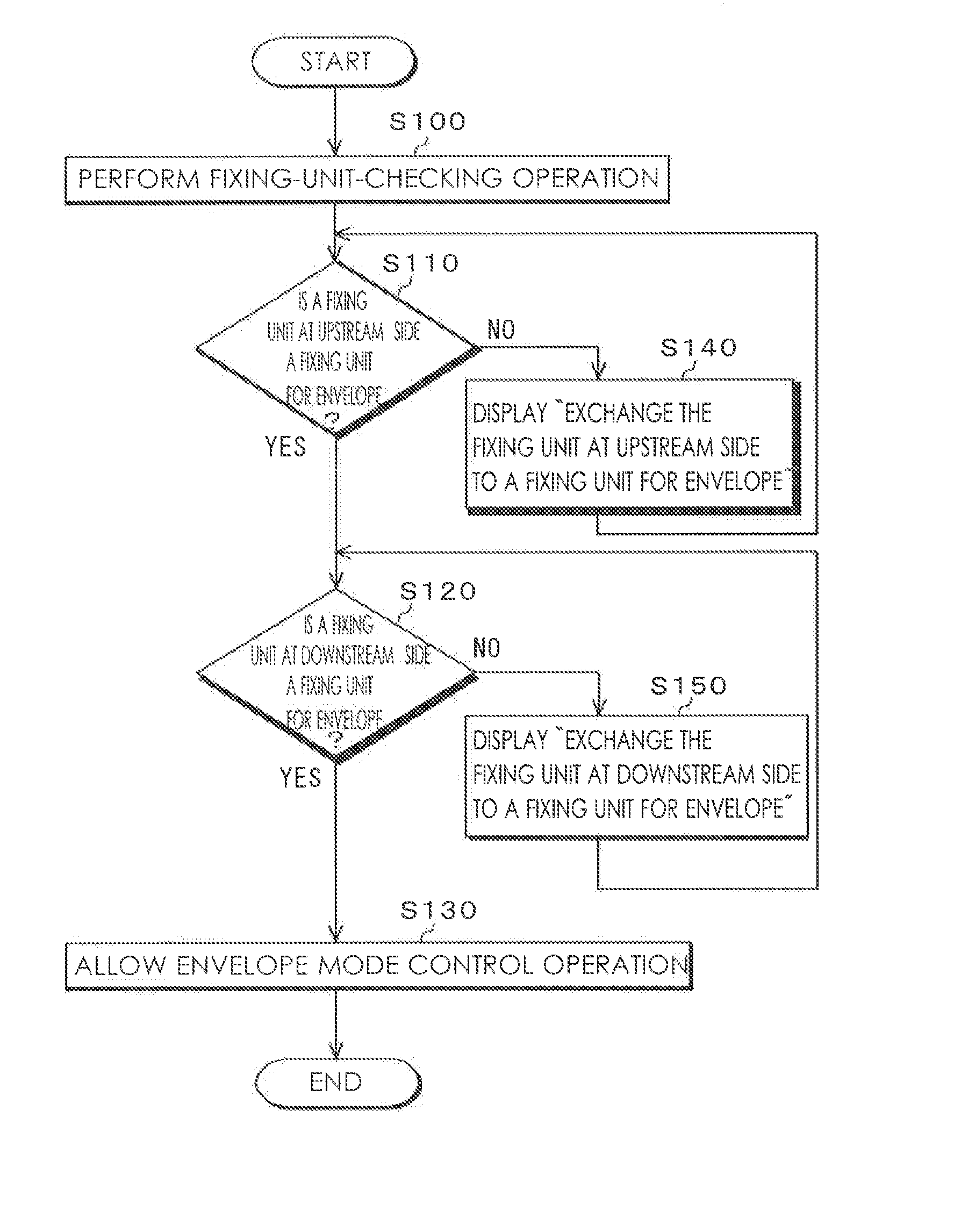
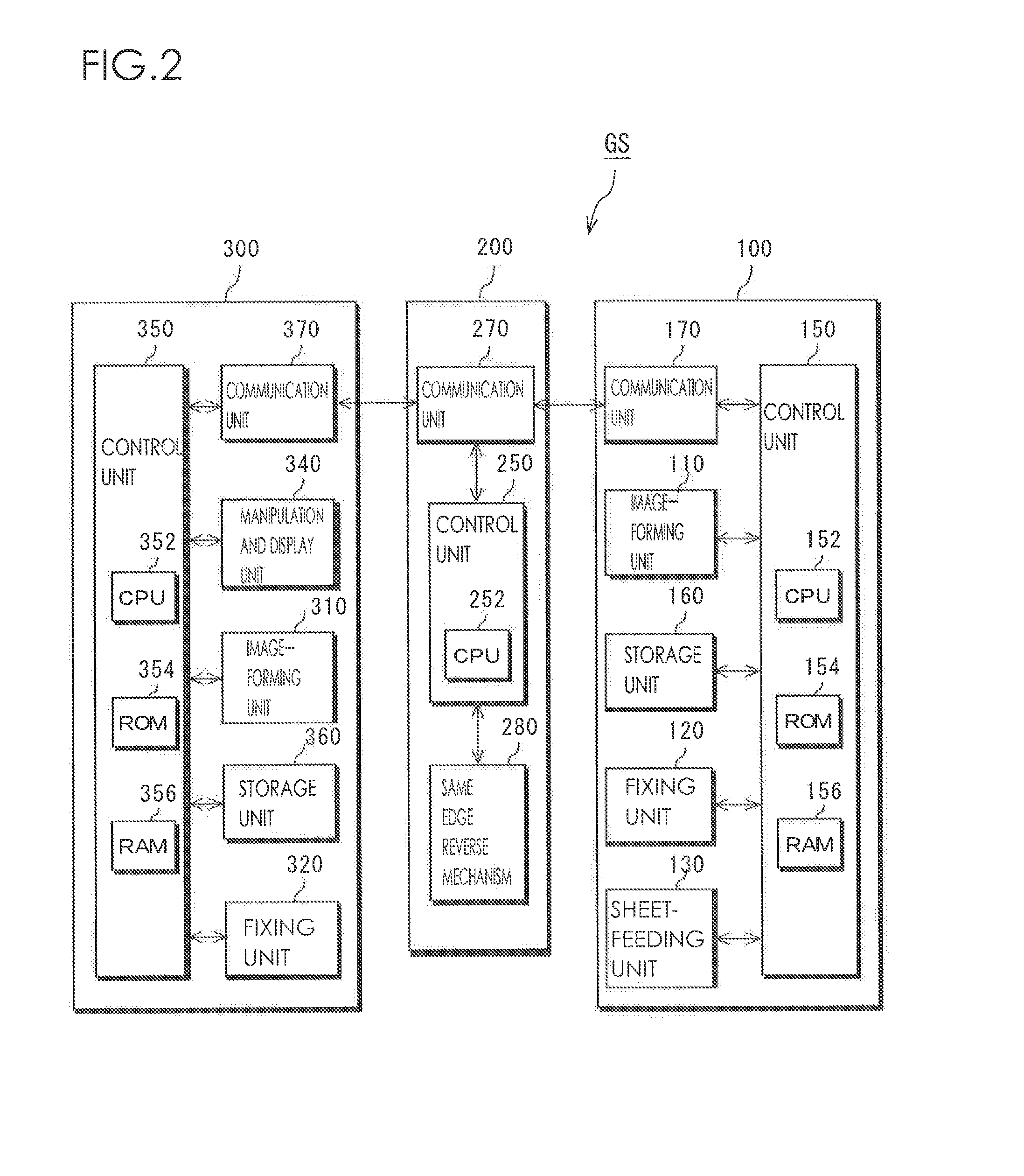
[0029]As shown in FIG. 1, the image forming apparatus GS is an image forming apparatus of tandem type in which a first copying portion 100, an intermediate transporting portion 200 and a second copying portion 300 are connected in series along a transporting direction D of a sheet of paper. A control portion of the image forming apparatus GS performs fixing-unit-checking operation, namely, checks a first fixing unit 120 in the first copying portion 100 at upstream side along the transporting direction D of the sheet ...
second embodiment
2. Second Embodiment
[0067]The second embodiment is different from the first embodiment. in that the control flow takes info consideration a case where neither, fixing unit of upstream side nor fixing unit of downstream side is a fixing unit for an envelope. It is to be noted that, other components and operations of the image forming apparatus 023 according to this embodiment are identical to those of the first embodiment so that the identical components are indicated by line same reference numbers, a detailed explanation of which will be omitted.
[0068]FIG. 4 snows an operation example of the image forming apparatus GS according to the second embodiment of this invention during an operation tune for checking fixing units. The following will describe a case where she control unit 150 of the second copying portion 300 is a main controller and controls the image forming apparatus GS together with the control unit 130 of the first copying portion 100 and the control unit 250 of the inter...
third embodiment
3. Third Embodiment
[0076]The third embodiment is different from the first embodiment in that a user can select the envelope mode or the regular mode on the management screen of the manipulation and display unit 340. It is to be noted that other components and operations of the image forming apparatus GS according to this embodiment are identical to those of the first embodiment so that the identical components are indicated by the same reference numbers, a detailed explanation of which will be omitted.
[0077][Configuration Example of Image Forming Apparatus GS]
[0078]The management screen (menu screen) of the manipulation and display unit 340 in the image forming apparatus GS according to the third embodiment of this invention includes a button for the regular mode to print or copy the images on the regular sheet of paper such as a sheet of paper of A3 or A4 size and a button for the envelope mode to print or copy the images on the envelope P, as a fixing operation, mode according to ...
PUM
 Abstract
Description
Claims
Application Information
 - R&D
- Intellectual Property
- Life Sciences
- Materials
- Tech Scout
- Unparalleled Data Quality
- Higher Quality Content
- 60% Fewer Hallucinations
Browse by: Latest US Patents, China's latest patents, Technical Efficacy Thesaurus, Application Domain, Technology Topic, Popular Technical Reports.
© 2025 PatSnap. All rights reserved.Legal|Privacy policy|Modern Slavery Act Transparency Statement|Sitemap|About US| Contact US: help@patsnap.com


