Image forming system

a technology of image forming and foil printing, which is applied in the direction of instruments, electrographic process equipment, optics, etc., can solve the problems of deteriorating productivity of foil printing, difficult to provide an image forming system, and difficulty in performing automatic foil printing using successive steps

Active Publication Date: 2013-11-21
KONICA MINOLTA INC
View PDF2 Cites 9 Cited by
  • Summary
  • Abstract
  • Description
  • Claims
  • Application Information

AI Technical Summary

Benefits of technology

[0013]This invention also has another object to provide another improved image forming system which performs foil transfer processing under automatic successive steps even when the sheet of paper or the desired positive toner image fails to align one with the other.

Problems solved by technology

As a result thereof, it is difficult to provide an image forming system in which only a desired target foil image is transferred.
It is difficult to perform the foil printing automatically using successive steps.
Further, since it is difficult to perform the foil printing steps successively, the productivity thereof may be deteriorated.
Further, in the past foil transferring method, when the foil image of the foil sheet is not aligned with the positive toner image having high accuracy, it is difficult to attain any desired foil processed image.
When such an alignment is performed by human power, it is difficult to do the alignment with high accuracy.
When the alignment is complete, it takes a long time.
Thus, it is difficult to perform the foil printing with high accuracy.

Method used


Image

  • Image forming system
  • Image forming system
  • Image forming system

Examples


first embodiment

[Configuration Example of Image Forming System]

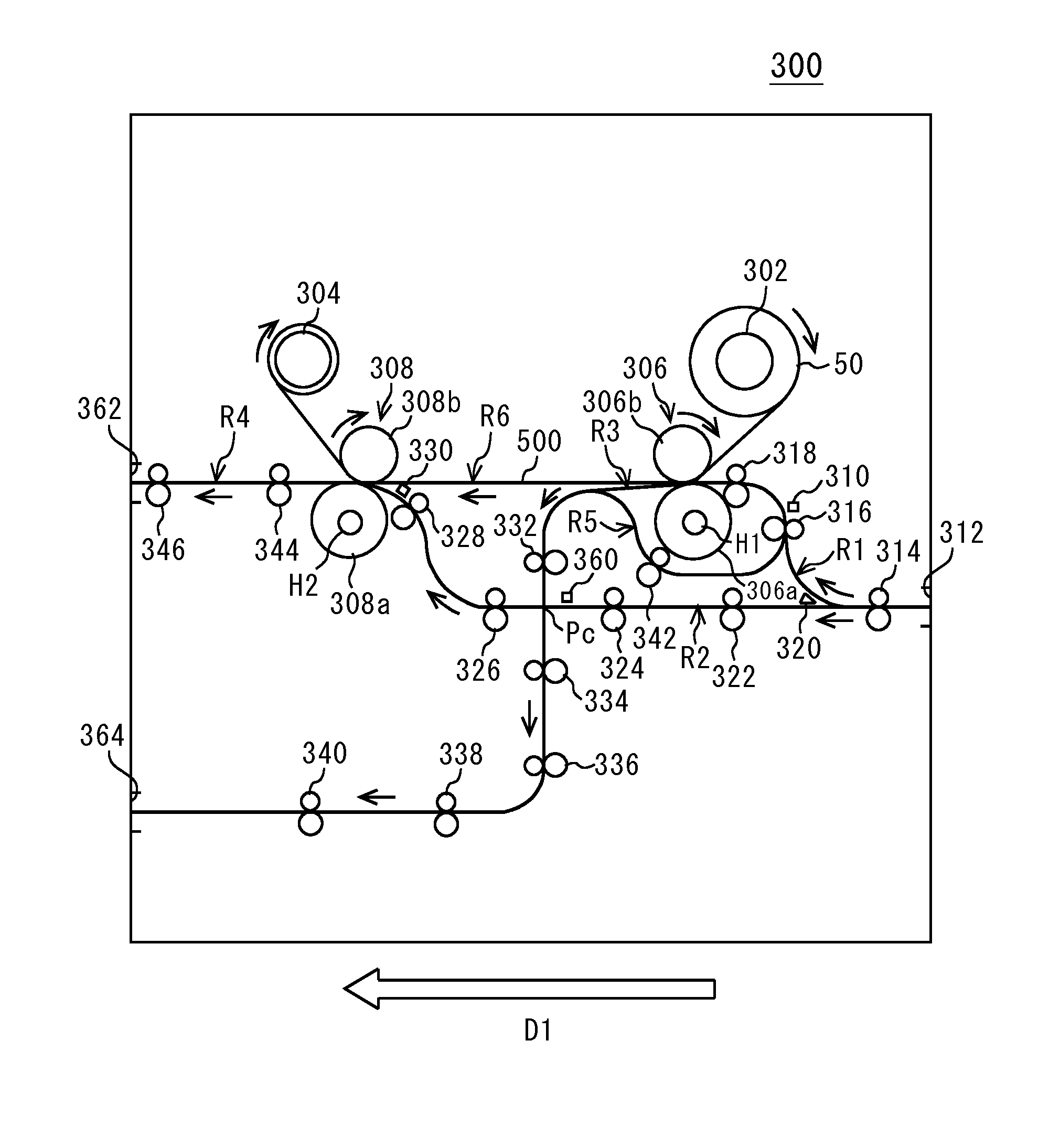
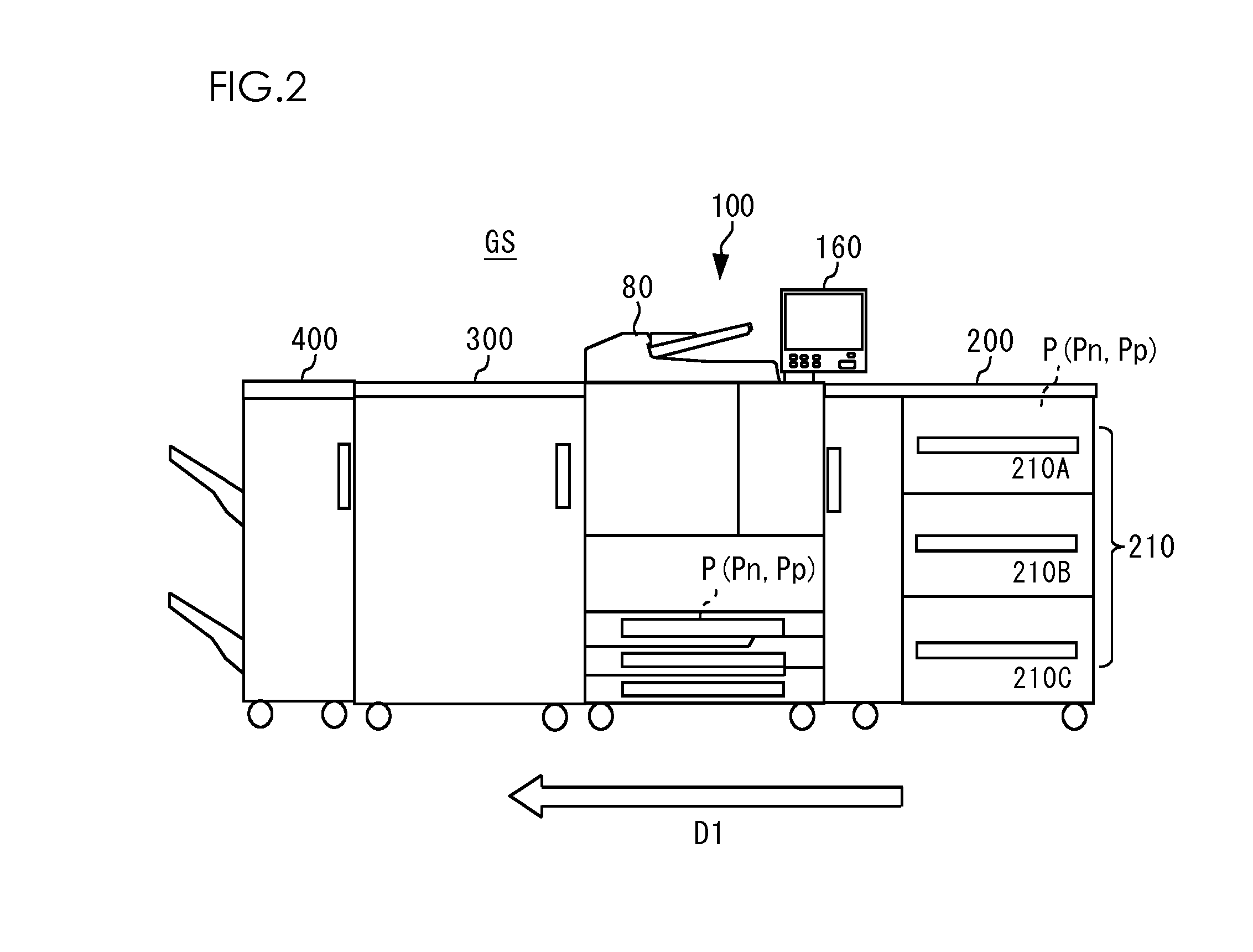
[0040]The following will describe a first embodiment of an image forming system GS relating to the invention with reference to drawings. FIG. 2 shows a configuration example of the image forming system GS. It is to be noted that a size and a ratio in each of the drawings are exaggerated reduced for convenience of explanation and the ratio or the like may be different from the actual one. As shown in FIG. 2, the image forming system GS according to the invention is provided with a large capacity feeder 200, an image forming apparatus 100, a foil transferring apparatus 300 and a finisher 400. In FIG. 2, a sign, “D1” indicates a sheet-conveying direction.

[0041]The large capacity feeder 200 connects the image forming apparatus 100 at an upstream side along the sheet-conveying direction D1 of a sheet of paper P. The large capacity feeder 200 contains plural feeding trays 210 which contain a large quantity of sheets of paper P. The feeding tr...

second embodiment

[0139]The second embodiment is different from the first embodiment in that the waste sheet of paper Pn has a size that is at least twice as large as that of the sheet of paper Pp and plural desired negative toner images are transferred on the waste sheet of paper Pn. It is to be noted that other configuration of the image forming system GS is identical to that of the above-mentioned first embodiment so that the common components are referred by the same symbols and their detailed explanation will be omitted.

[Configuration Example of Waste Sheet of Paper Pn as First Base Material]

[0140]The following will describe the configuration example of waste sheet of paper Pn used in the foil transfer processing of the image forming system GS according to the second embodiment of this invention. FIG. 14A shows the configuration example of the waste sheet of paper Pn used in the second embodiment. FIG. 14B is a sectional view thereof, taken along lines D-D. It is to be noted that in FIGS. 14A an...

third embodiment

[0155]The third embodiment is different from the first embodiment in that transparent toner is used in the image forming portion 10 and an enlarged toner image is used as the desired positive toner image. It is to be noted that other configuration of the image forming system GS is identical to that of the above-mentioned first embodiment so that the common components are referred by the same symbols and their detailed explanation will be omitted.

[Configuration Example of Image Forming System]

[0156]The following will describe a configuration example of the image forming system GS according to the third embodiment of this invention. The image forming system GS according to the third embodiment of this invention may be configured so as to be identical to that of the first embodiment of this invention as shown in FIG. 2 so that the description of common components will be omitted.

[0157]The manipulation / display portion 160 allows the user to set a contour region, to be enlarged, of the d...


PUM


Abstract

An image forming apparatus transfers a negative toner image on a waste sheet of paper having larger size than that of a printing sheet of paper and transfers all the toner images on the printing sheet of paper. A first thermal transferring portion transfers an unnecessary foil of a foil sheet on the negative toner image of the waste sheet of paper image. A second thermal transferring portion transfers a foil remained on the foil sheet on the positive toner image of the printing sheet of paper. The positive toner image is formed using transparent toner. Any gradation processing is performed on an edge of the positive toner image.

Description

CROSS REFERENCE TO RELATED APPLICATION[0001]The present invention contains subject matters related to Japanese Patent Application Nos. JP 2012-113530, JP2013-67454, JP2012-142051 and JP2013-67455 filed in the Japanese Patent Office on May 17, 2012, Jun. 25, 2012 and Mar. 27, 2013, the entire contents of which being incorporated herein by reference.BACKGROUND OF THE INVENTION[0002]1. Field of the Invention[0003]The present invention relates to an image forming system, in which a desired foil image is transferred on a desired toner image on base material on which an image has been formed.[0004]2. Description of Related Art[0005]In a bookbinding field, a commercial printing field, a card business field or a plastic molding field such as cosmetic container, printing has been performed such that a character and / or a picture image made of foil are transferred to the sheet of paper in order to give metallic appearance or a high-quality glossy image to a product, which cannot be expressed m...

Claims


Application Information

Patent Timeline
Patent Type & Authority Applications(United States)
IPC IPC(8): G03G15/20
CPCG03G15/16G03G15/225G03G21/04
Inventor SUZUKI, TOMOO
Owner KONICA MINOLTA INC
Why Eureka
Try Eureka