
Image processing apparatus and image processing method

Active Publication Date: 2010-04-15
CANON KK
View PDF29 Cites 80 Cited by
  • Summary
  • Abstract
  • Description
  • Claims
  • Application Information

AI Technical Summary

Benefits of technology

[0016]The present invention has been made to solve at least one of the conventional problems. Embodiments of the present invention provide an aberration correction method, image processing apparatus, and image processing system capable of performing aberration correction suited to each observer and presenting an aberration (color misregistration)-reduced display image in an image display apparatus having a display optical system which enlarges an image formed on a display device and allows an observer to observe it.

Problems solved by technology

A lens with good optical characteristics designed to prevent these aberrations is generally expensive.
However, these conventional techniques suffer the following problems.
However, when an observer who uses a powerful vision correction optical system observes the same corrected image, he observes the color misregistration even on the corrected image.
However, the conventional techniques cannot meet this requirement.
However, it is difficult to directly apply the above-mentioned conventional techniques to compact apparatuses such as an EVF and HMD to obtain optical characteristics including aberrations of a vision correction optical system.

Method used


Image

  • Image processing apparatus and image processing method
  • Image processing apparatus and image processing method
  • Image processing apparatus and image processing method

Examples


first embodiment

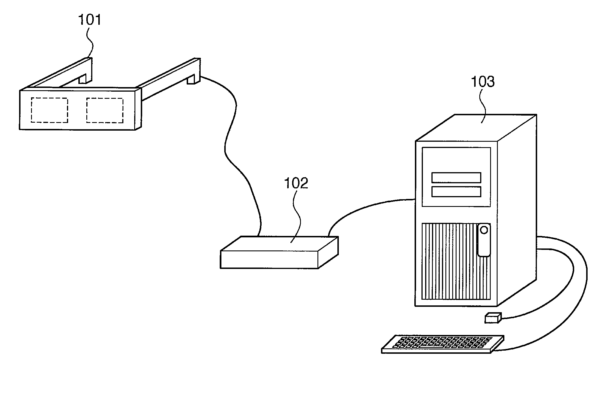
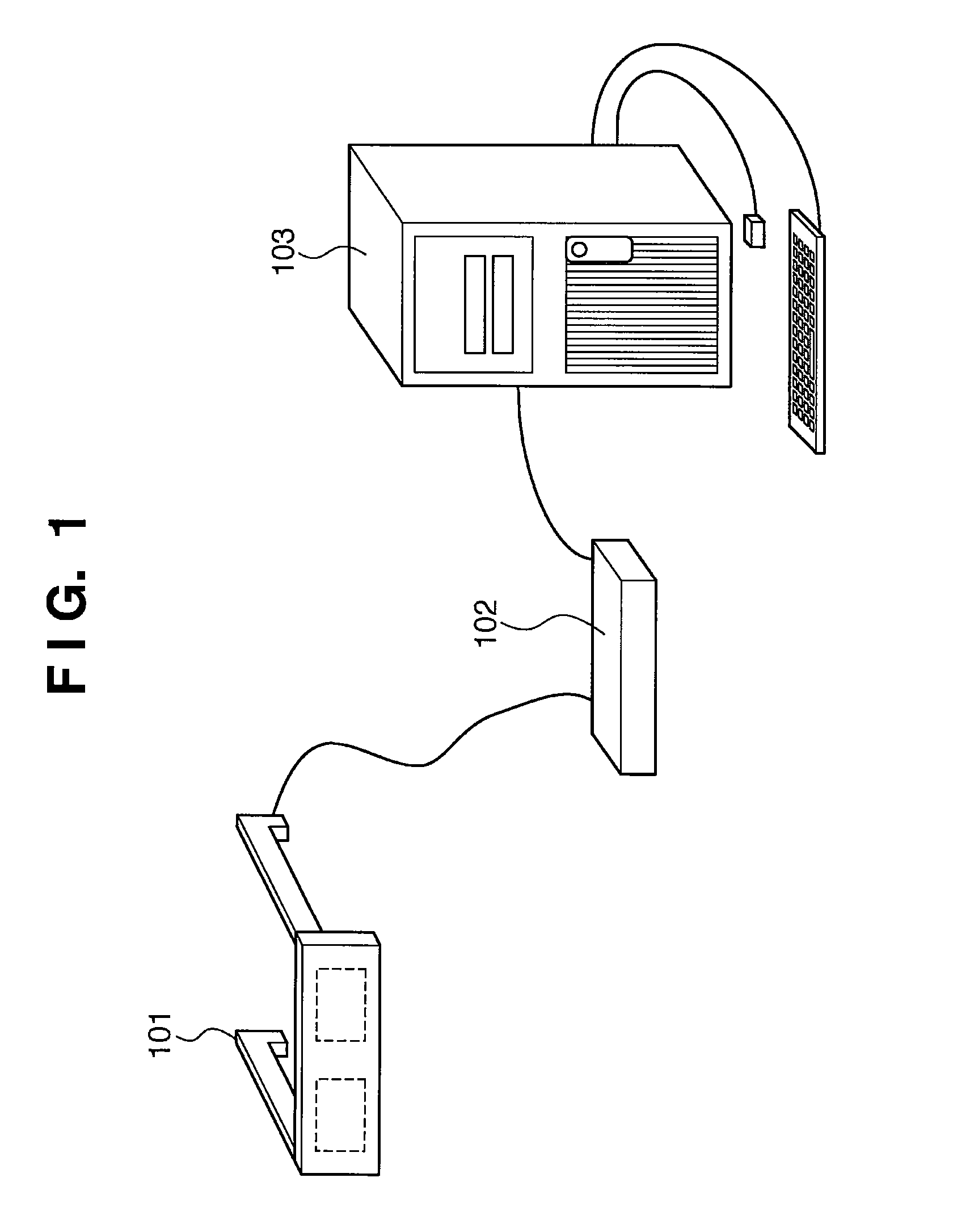
[0045]FIG. 1 is a view exemplifying the configuration of an image processing system using an HMD in the first embodiment. The image processing system in the first embodiment may be a hand-held display apparatus, like binoculars, and an application of the present invention is not limited to a head mounted display.

[0046]The present invention is applicable to all display apparatuses each having an enlargement optical system which enlarges (as a virtual image) a display image formed on a display device and allows an observer to observe it. An example of these display apparatuses is an EVF attached to a digital camera or the like.

[0047]An image processing system using an HMD as an image display apparatus is superior to one using a general display in providing an observer with full immersion into an image and high realistic sensation. In recent years, a so-called mixed reality (to be referred to as MR) technique is known as an example of image processing systems using HMDs. This technique...

second embodiment

[0256]The second embodiment will be described with reference to the accompanying drawings.

[0257]In the first embodiment, if in S1404 the color misregistration does not fall within an allowable range then in S1405 and S1406 two correction values corresponding to correction amounts close to an obtained amount of color misregistration are selected from aberration correction values (correction tables) prepared in advance. A new correction value is newly generated by interpolation calculation of the two correction values, and then appropriate aberration correction is executed. In the second embodiment, a new correction value is generated based on one aberration correction value (a correction table or a parameter table of an approximate polynomial), and proper correction is performed. While maintaining the same correction precision as that in the first embodiment, the second embodiment reduces a necessary memory by decreasing the number of aberration correction values prepared in advance....

third embodiment

[0274]The third embodiment will be described with reference to the accompanying drawings. In the first and second embodiments, aberration correction is executed for each user by newly generating a correction value from aberration correction values prepared in advance, based on the obtained amount of color misregistration. In the third embodiment, an optimum aberration correction value is selected from aberration correction values prepared in advance to perform correction. The third embodiment can downsize the circuit without any complicated calculation. The third embodiment does not require an operation to obtain the amount of color misregistration, and can simplify a operation by the HMD user according to the embodiment. The third embodiment will be described mainly with respect to this feature.

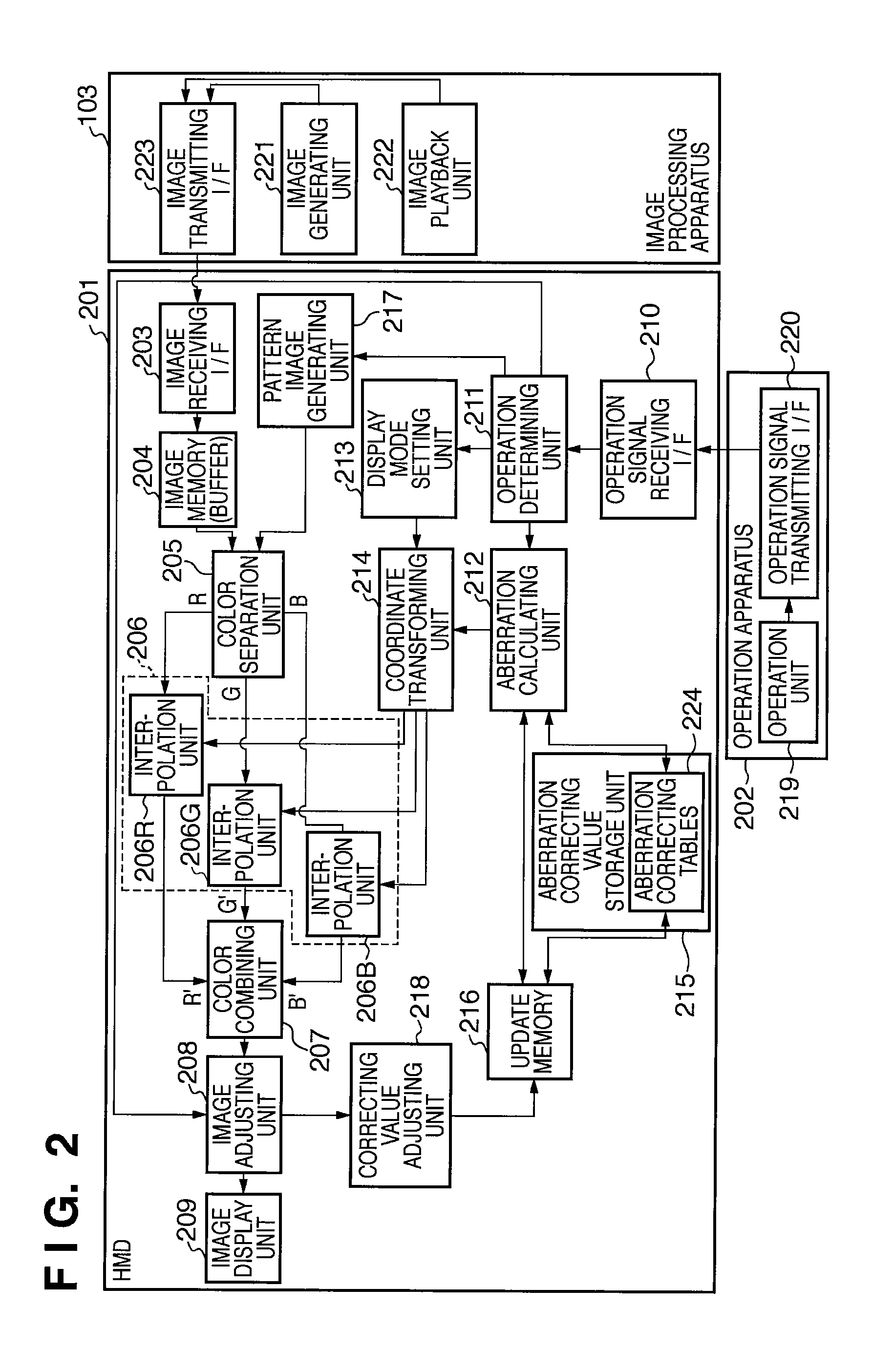
[0275]FIG. 18 is a functional block diagram of an HMD in the third embodiment. An image processing apparatus 103 is the same as that in the first embodiment, and is consequently not illustra...


PUM


Abstract

Units which respectively acquire information on an aberration generated by a display optical system and information on an aberration generated by a vision correction optical system used by an observer are arranged. Aberration correction is executed based on the two aberrations. An aberration generated by a combination of the display optical system and the vision correction optical system used by the observer can be appropriately corrected for each observer.

Description

BACKGROUND OF THE INVENTION[0001]1. Field of the Invention[0002]The present invention relates to an image processing apparatus. Particularly, the present invention is suitable to correct, for each observer, aberrations generated in an image display apparatus (e.g., HMD or EVF) having a display optical system which enlarges an image formed on a display device and allows an observer to observe the enlarged image.[0003]2. Description of the Related Art[0004]Many techniques have been proposed to digitally correct distortion of an image and color misregistration (bleeding) caused by aberrations generated by an optical lens. A lens for canceling aberrations is newly necessary to optically correct the distortion and color misregistration, increasing the size of the optical system. A lens with good optical characteristics designed to prevent these aberrations is generally expensive. Instead of such a lens, aberrations generated by an optical system are generally corrected by a digital aberr...

Claims


Application Information

Patent Timeline
IPC IPC(8): G09G5/00
CPCG02B27/0068G02B27/01G02B27/0101G09G2340/0464G02B2027/014G02B27/0172G09G5/38G02B2027/011
Inventor OYAMA, KENJITSUJIMOTO, TAKUYA
Owner CANON KK
Learn More