Check patentability & draft patents in minutes with Patsnap Eureka AI!

Vacuum cleaner floor seal

a vacuum cleaner and floor seal technology, applied in vacuum cleaners, mechanical cleaning, textiles and paper, etc., can solve the problems of reducing cleaning performance, reducing the use cost of prior devices, and reducing the cleaning effect of vacuum cleaners

Active Publication Date: 2013-06-13
MIDEA AMERICA CORP
View PDF3 Cites 31 Cited by
  • Summary
  • Abstract
  • Description
  • Claims
  • Application Information

AI Technical Summary

Benefits of technology

The vacuum cleaner suction head has a unique design with a housing, supports, and sealing plates. The sealing plates are movable between raised and lowered positions, and can be raised by contact with debris on the surface being cleaned. The technical effects of this design include improved vacuum performance, compact size, and better maneuverability on various types of floors.

Problems solved by technology

Such devices may include a brushroll cutoff mechanism to turn off the rotating brush when the device is in the bare floor cleaning position, as it has been found that on bare floors a brush can strike particles and project them away from the suction inlet, resulting in decreased cleaning performance.
Prior efforts to provide improved cleaning on various surfaces have not necessarily resulted in a universal cleaning solution that is optimized for all cleaning surfaces.
Such prior devices also may be excessively expensive to implement, complicated to use, or not suitable for the dirty environment in which vacuum cleaners operate.

Method used


Image

  • Vacuum cleaner floor seal
  • Vacuum cleaner floor seal
  • Vacuum cleaner floor seal

Examples


Embodiment Construction

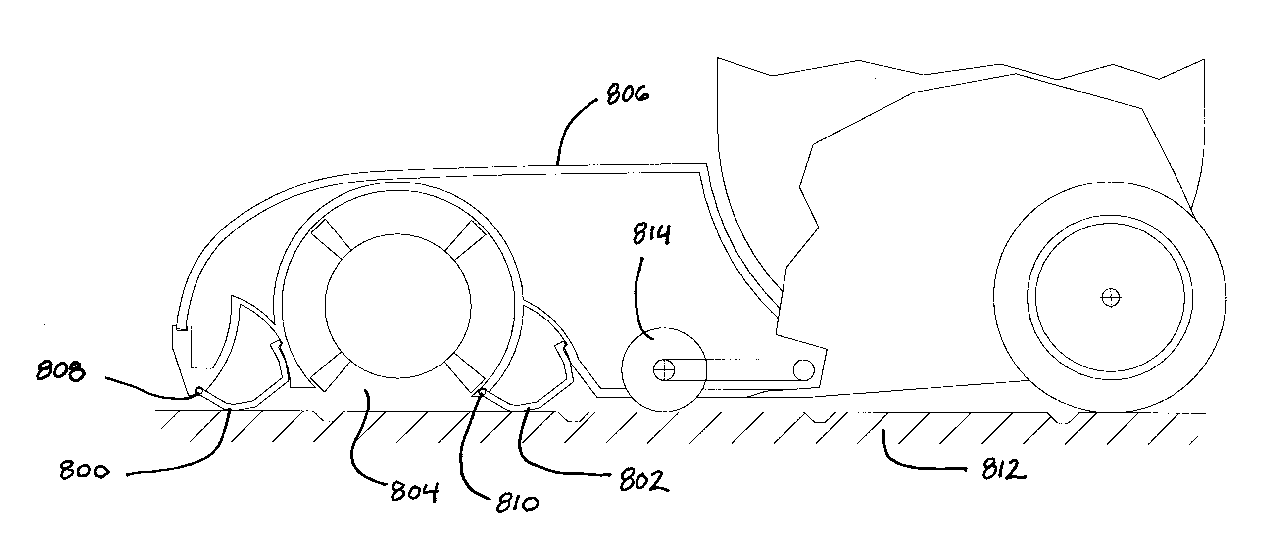
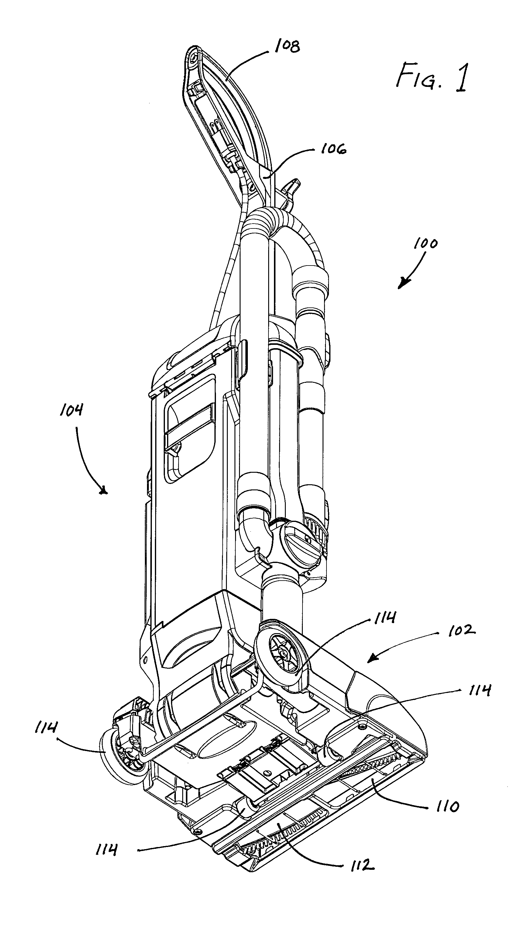
[0025]The present disclosure provides inventive features for vacuum cleaners, particularly relating to the suction inlet for the air flow path. Embodiments of the inventions described herein may be used with any kind of vacuum cleaner, such as upright vacuums, canister vacuums, stick vacuums, wet extractors, handheld cleaning accessories, central vacuum cleaning heads, and so on. A number of these features and alternative embodiments of the invention are described with reference to their exemplary use in an upright vacuum cleaner, such as the vacuum cleaner 100 shown in FIG. 1. It will be appreciated, however, that the features described herein can be used with vacuum cleaners having different configurations. Furthermore, the various features described herein may be used separately from one another or in any suitable combination. The present disclosure illustrating the use of the various inventions described herein is not intended to limit the inventions in any way.

[0026]FIG. 1 illu...


PUM


Abstract

A vacuum cleaner suction head having a housing, one or more support to support the housing on a surface to be cleaned, a suction inlet and front and rear sealing plates. The front and rear sealing plates extend along the front and rear edges of the suction inlet, respectively. the sealing plates are movable between raised positions in which the lower surfaces of the plates are close to the housing, and lowered positions in which the lower surfaces of the plates are remote from the housing. The front and rear plates are movable from the lowered position to the raised position by contact with debris on the surface to be cleaned.

Description

FIELD OF THE INVENTION[0001]The present invention relates to features for use with vacuum cleaners, such as upright vacuum cleaners, commercial vacuums, wet extractors, stick vacuums, canister vacuums, central vacuums, and the like.BACKGROUND OF THE INVENTION[0002]Vacuum cleaning devices, such as upright and canister vacuum cleaners, wet extractors, stick vacuums, electric brooms and other devices, are in widespread use as tools to clean floors, upholstery, stairs, and other surfaces. Vacuum cleaners typically are expected to operate on various different floor surfaces, such as carpets, hardwood, tiles, and so on. Furthermore, vacuum cleaners typically are expected to be able to remove debris having a wide variety of physical shapes and properties. The debris found in a typical household can include wet substances (e.g., mud and water-soaked hair or dirt), dry particles (e.g., dust and lint), fibers (e.g., hair and carpet fibers) and food particles (e.g., crumbs, popcorn kernels, po...

Claims


Application Information

Patent Timeline
IPC IPC(8): A47L9/00A47L5/00
CPCA47L9/02A47L5/30A47L9/0477
Inventor DAVIDSHOFER, DONALDJOSEFSSON, THOMAS
Owner MIDEA AMERICA CORP
Features
  • R&D
  • Intellectual Property
  • Life Sciences
  • Materials
  • Tech Scout
  • Unparalleled Data Quality
  • Higher Quality Content
  • 60% Fewer Hallucinations
Learn More