Electronic device enclosure

a technology for electronic devices and enclosures, applied in the direction of electrical apparatus casings/cabinets/drawers, instruments, etc., can solve the problems of laborious and time-consuming screws and screws

Inactive Publication Date: 2013-06-13
HONG FU JIN PRECISION IND WUHAN CO LTD +1
View PDF6 Cites 10 Cited by
  • Summary
  • Abstract
  • Description
  • Claims
  • Application Information

AI Technical Summary

Problems solved by technology

Using screws is very laborious and time-consuming.

Method used


Image

  • Electronic device enclosure
  • Electronic device enclosure
  • Electronic device enclosure

Examples


Embodiment Construction

[0014]The disclosure is illustrated by way of example and not by way of limitation in the figures of the accompanying drawings in which like references indicate similar elements. It should be noted that references to “an” or “one” embodiment in this disclosure are not necessarily to the same embodiment, and such references mean at least one.

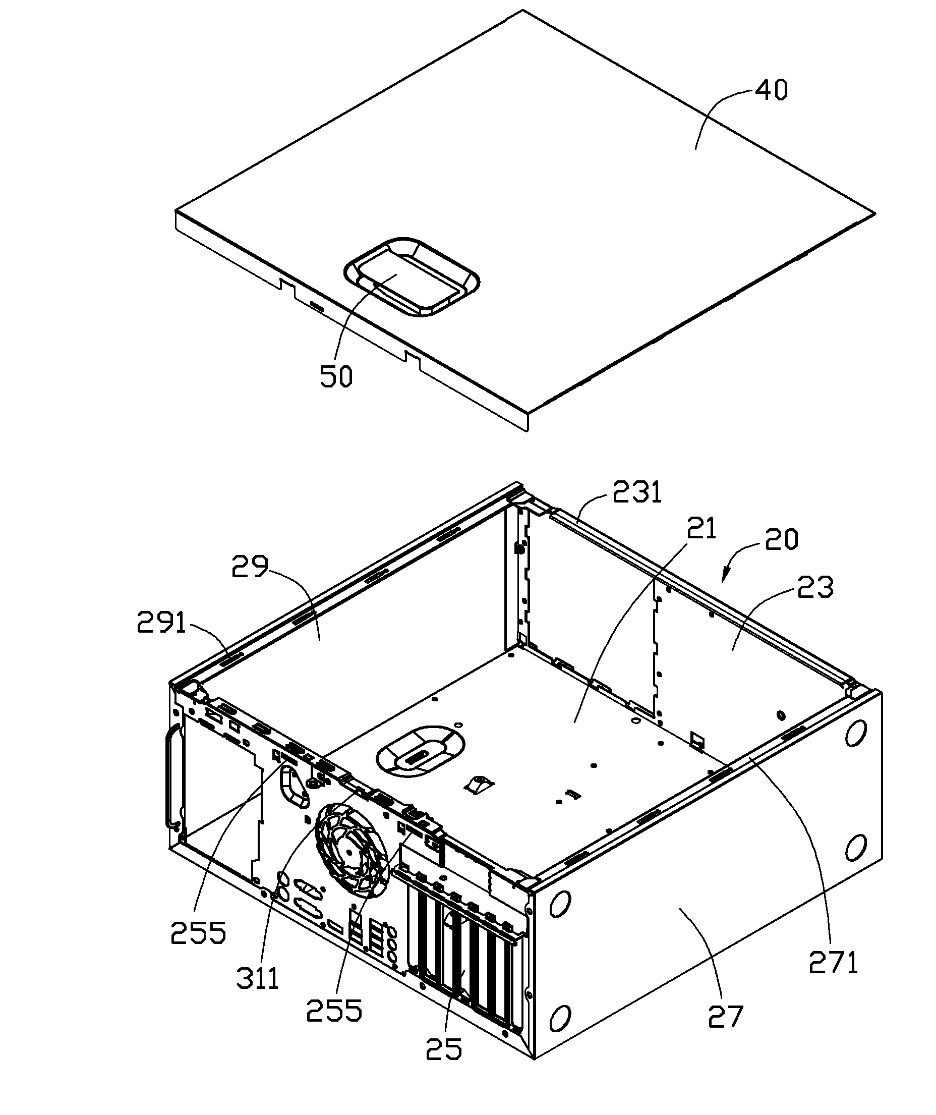
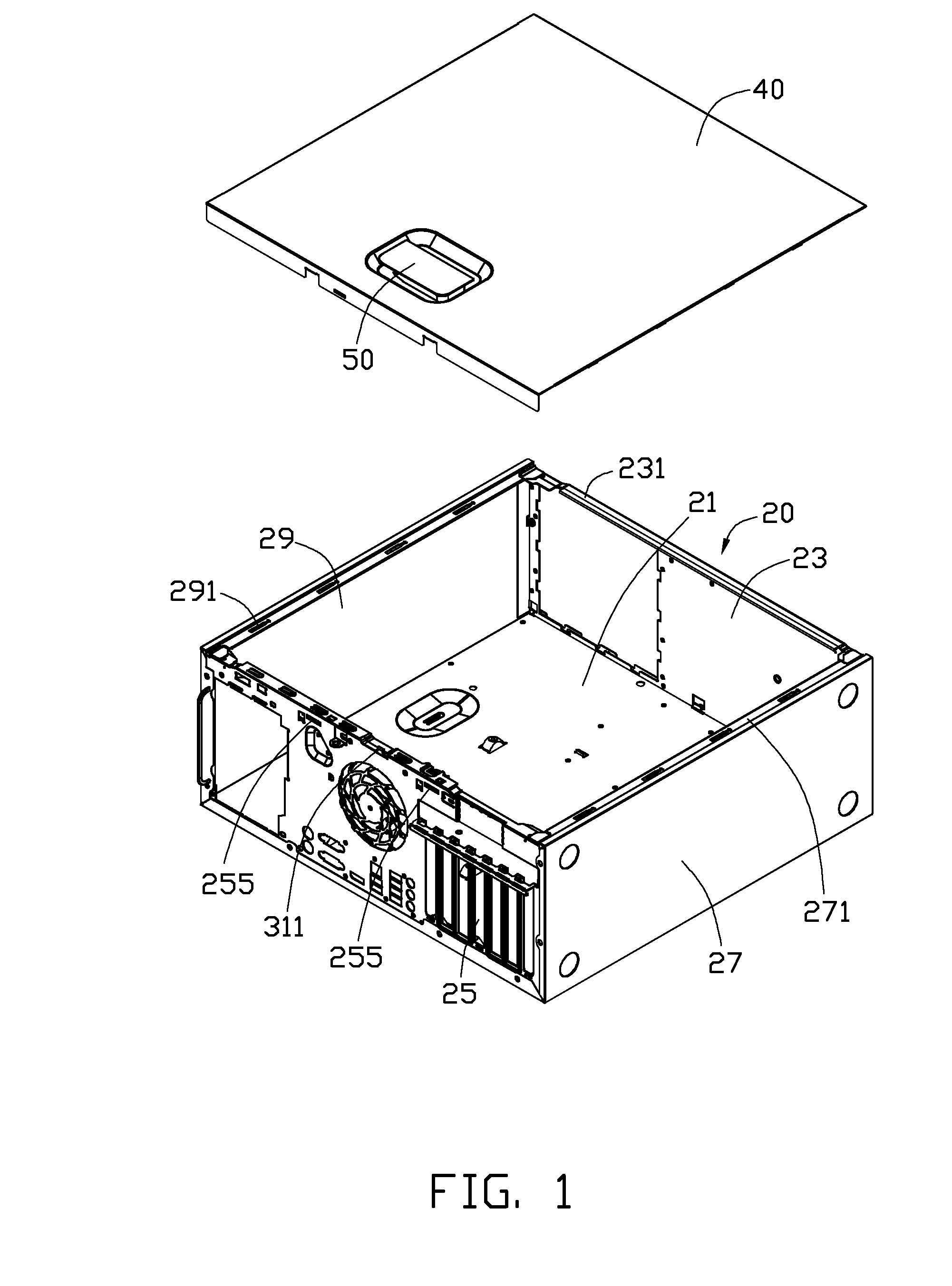
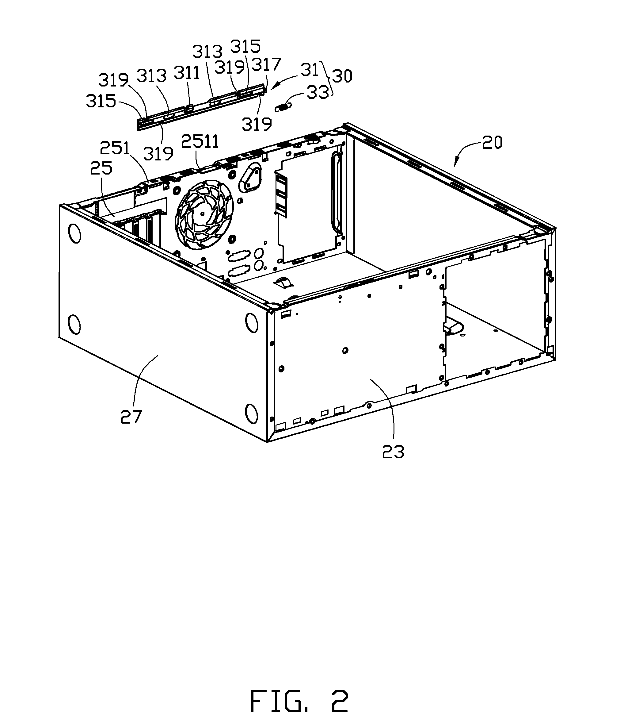
[0015]FIGS. 1-5 illustrate an electronic device enclosure in accordance with an embodiment. The electronic device enclosure includes a base 20, a clipping device 30 attached to the base 20, a side plate 40 attached to the base 20, and a rotating device 50 rotatably attached to the side plate 40.

[0016]Referring to FIG. 2, the base 20 includes a bottom plate 21, a front plate 23, a rear plate 25, a first side plate 27, and a second side plate 29. The front plate 23 and the rear plate 25 are connected to two opposite sides of the bottom plate 21. The first side plate 27 and the second side plate 29 are connected to another two opposite sides of the ...


PUM


Abstract

An electronic device enclosure includes a rear plate defining a through hole, a side plate having a hook, a clipping device, and a rotating device. The clipping device includes a clipping member and a first resilient member. The clipping member may slide relative to the rear plate between a lock position and an unlock position. When the clipping member is located in the clock position, the hook is engaged in the through hole. When the clipping member is located in the unlock position, the hook is disengaged from the through hole. The rotating device is rotatably coupled to the side plate and may drive the clipping member to slide from the lock position to the unlock position. The first resilient member may drive the clipping member to slide from the unlock position to the lock position.

Description

BACKGROUND[0001]1. Technical Field[0002]The present disclosure relates to an electronic device enclosure.[0003]2. Description of Related Art[0004]An electronic device enclosure, such as a personal computer case, often includes a base and a side plate secured to the base with a plurality of screws. Using screws is very laborious and time-consuming. Therefore, there is room for improvement within the art.BRIEF DESCRIPTION OF THE DRAWINGS[0005]Many aspects of the embodiments can be better understood with references to the following drawings. The components in the drawings are not necessarily drawn to scale, the emphasis instead being placed upon clearly illustrating the principles of the embodiments. Moreover, in the drawings, like reference numerals designate corresponding parts throughout the several views.[0006]FIG. 1 is an isometric view of an electronic device enclosure in accordance with an embodiment.[0007]FIG. 2 is an exploded, isometric view of a base and a clipping device of ...

Claims


Application Information

Patent Timeline
Patent Type & Authority Applications(United States)
IPC IPC(8): H05K5/00
CPCG06F1/181
Inventor CHEN, YUN-LUNGCHAI, CHUNGSUN, DA-LONG
Owner HONG FU JIN PRECISION IND WUHAN CO LTD
Why Eureka
Try Eureka