Mounting apparatus for computer keyboard

a technology for mounting apparatuses and computer keyboards, which is applied in the field of mounting apparatuses, can solve the problems of laborious and time-consuming process of assembling or dismounting apparatuses for the keyboard

Inactive Publication Date: 2013-07-04
HONG FU JIN PRECISION IND (SHENZHEN) CO LTD +1
View PDF10 Cites 1 Cited by
  • Summary
  • Abstract
  • Description
  • Claims
  • Application Information

AI Technical Summary

Benefits of technology

The patent text describes a mounting apparatus for a computer keyboard that is designed to make assembly and disassembly easier and faster. The apparatus includes a base and a supporting member with a receiving member attached to it. The supporting member has a supporting plate with a rectangular opening for installing the keyboard. The opening has flanges that define through holes for inserting the keyboard's tabs. The apparatus also includes resilient blocks with a resilient portion and a latch portion. The resilient portion extends from the flanges and has an oblique-guiding surface. The latch portion is located on one side of the resilient portion and adjacent to the free end. The technical effect of this design is that it allows for easier and faster assembly and disassembly of the keyboard, reducing the time and effort required for assembly and disassembly.

Problems solved by technology

The process to assemble or dismounting apparatus the keyboard is very laborious and time-consuming.

Method used


Image

  • Mounting apparatus for computer keyboard
  • Mounting apparatus for computer keyboard
  • Mounting apparatus for computer keyboard

Examples


Embodiment Construction

[0014]The disclosure is illustrated by way of example and not by way of limitation in the figures of the accompanying drawings in which like references indicate similar elements. It should be noted that references to “an” or “one” embodiment in this disclosure are not necessarily to the same embodiment, and such references mean at least one.

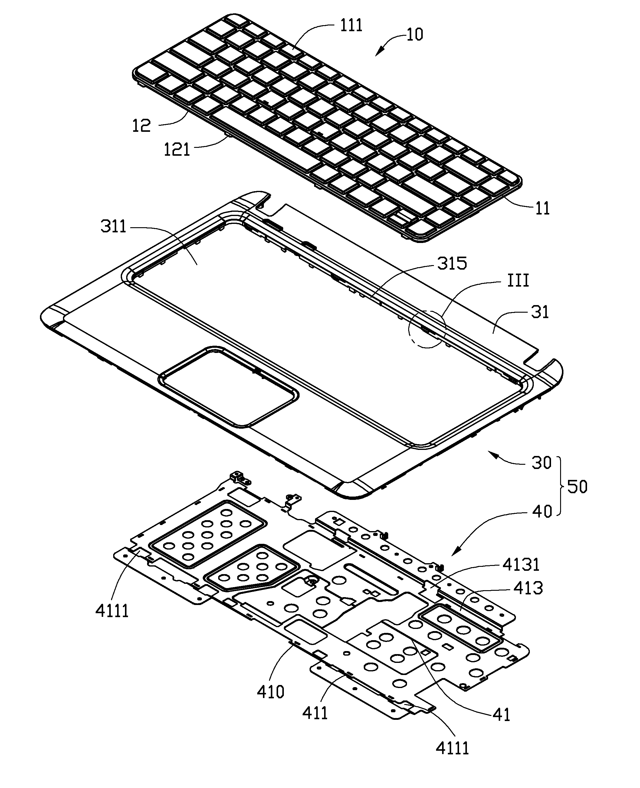
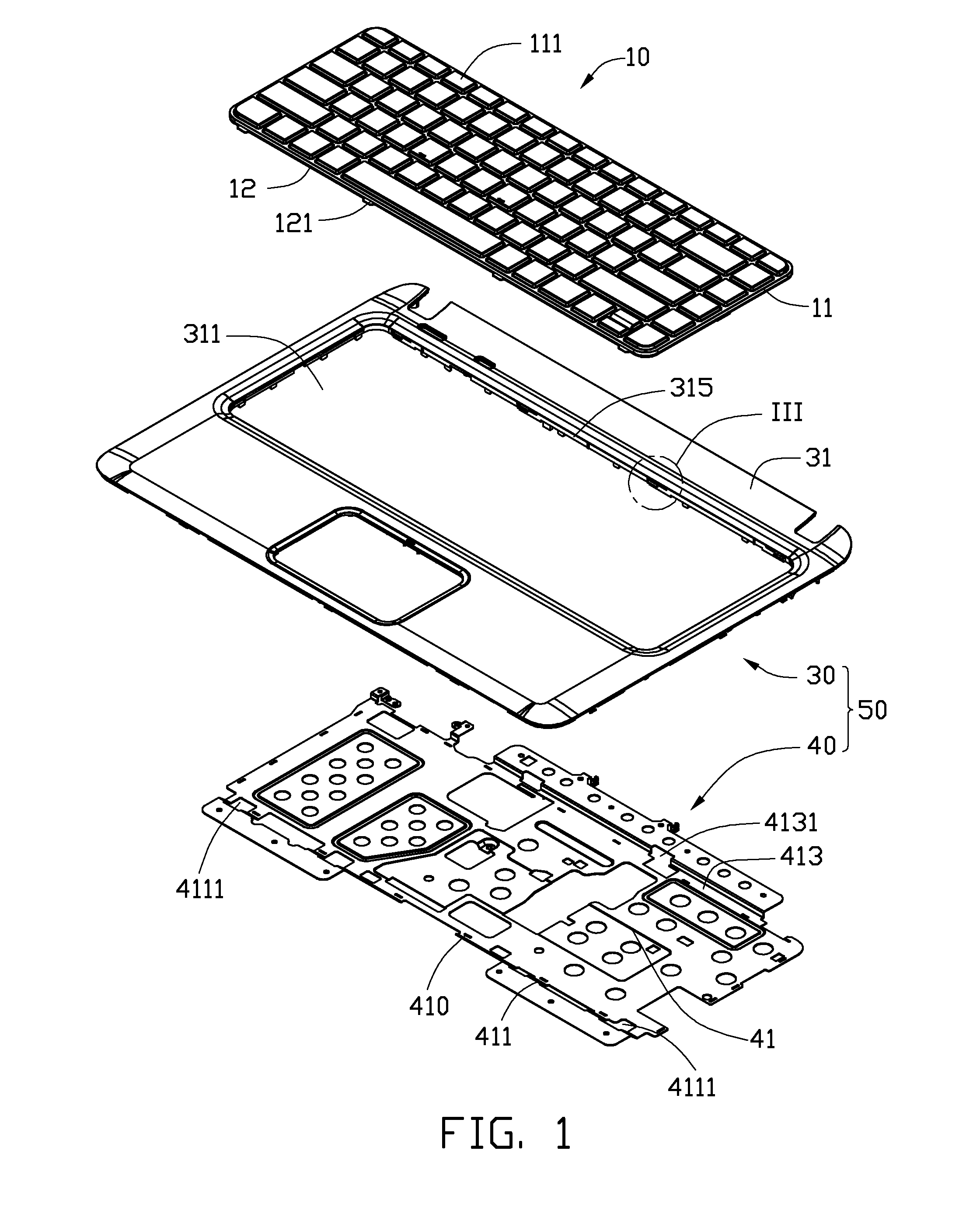
[0015]FIG. 1-2 illustrate an embodiment of a mounting apparatus configured to secure a keyboard 10.

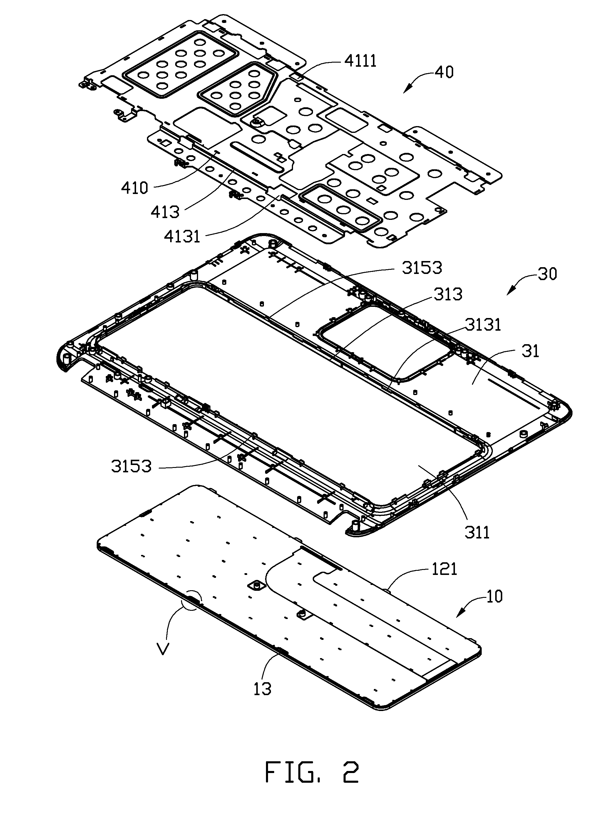
[0016]The keyboard 10 includes a bezel 11. A plurality of keys 111 are located on the bezel 11. The bezel 11 has a first edge 12 and a second edge 13 opposite to the first edge 12. In one embodiment, the bezel 11 is substantially rectangular. Four inserting tabs 121 extend from the first edge 12. The second edge 13 defines four latch slots 131(shown in FIG. 5).

[0017]The mounting apparatus includes a base 50. The base 50 includes a supporting member 30 and a receiving member 40 attached to the supporting member 30.

[0018]The supporting member 30 inclu...


PUM


Abstract

A mounting apparatus for a keyboard includes a supporting member and a receiving member. The supporting member includes a supporting plate and a plurality of resilient blocks located on the supporting plate. The receiving member is attached to the supporting plate and includes a receiving portion configured to receive the keyboard and defining a plurality of receiving holes. Each of the plurality of resilient blocks is received in each of the plurality of receiving holes. Each of the plurality of resilient blocks extends through each of the plurality of receiving holes to abuts the keyboard, for preventing the keyboard from disengagement the receiving portion. Each of the plurality of resilient blocks is resiliently deformable to disengage from the keyboard, to release the keyboard.

Description

BACKGROUND[0001]1. Technical Field[0002]The present disclosure relates to mounting apparatuses, and particularly to a mounting apparatus for a computer keyboard.[0003]2. Description of Related Art[0004]A typical personal computer includes a keyboard and a base. The keyboard may be attached to the base with screws. A tool, such as a screwdriver, is needed to fasten or unfasten the screws to assemble or disassemble the keyboard. The process to assemble or dismounting apparatus the keyboard is very laborious and time-consuming.[0005]Therefore, there is room for improvement within the art.BRIEF DESCRIPTION OF THE DRAWINGS[0006]Many aspects of the embodiments can be better understood with references to the following drawings. The components in the drawings are not necessarily drawn to scale, the emphasis instead being placed upon clearly illustrating the principles of the embodiments. Moreover, in the drawings, like reference numerals designate corresponding parts throughout the several ...

Claims


Application Information

Patent Timeline
IPC IPC(8): H05K7/14
CPCY10T403/60G06F1/1662
Inventor DAI, QIANG-WU
Owner HONG FU JIN PRECISION IND (SHENZHEN) CO LTD
Why Eureka
Try Eureka