Roller shade counter balancing and blind attaching method and apparatus

Inactive Publication Date: 2013-07-18
HOMERUN HLDG
View PDF9 Cites 3 Cited by
  • Summary
  • Abstract
  • Description
  • Claims
  • Application Information

AI Technical Summary

Benefits of technology

[0006]The foregoing needs are met, to a great extent, by some embodiments of the present invention. Wherein in one aspect, an apparatus is provided that, in some embo

Problems solved by technology

While this may be effective in allowing the shade material to be attached to the roller assembly, it can also provide undesired characteristics.
For example, it may be difficult to separate the shade materia

Method used


Image

  • Roller shade counter balancing and blind attaching method and apparatus
  • Roller shade counter balancing and blind attaching method and apparatus
  • Roller shade counter balancing and blind attaching method and apparatus

Examples


Example

[0020]The invention will now be described with reference to the drawing figures, in which like reference numerals refer to like parts throughout. An embodiment in accordance with the present invention provides a method and apparatus for attaching blind or shade material to a roller assembly. Further, a method and apparatus is also shown and described that may be used to counter balance a roller assembly.

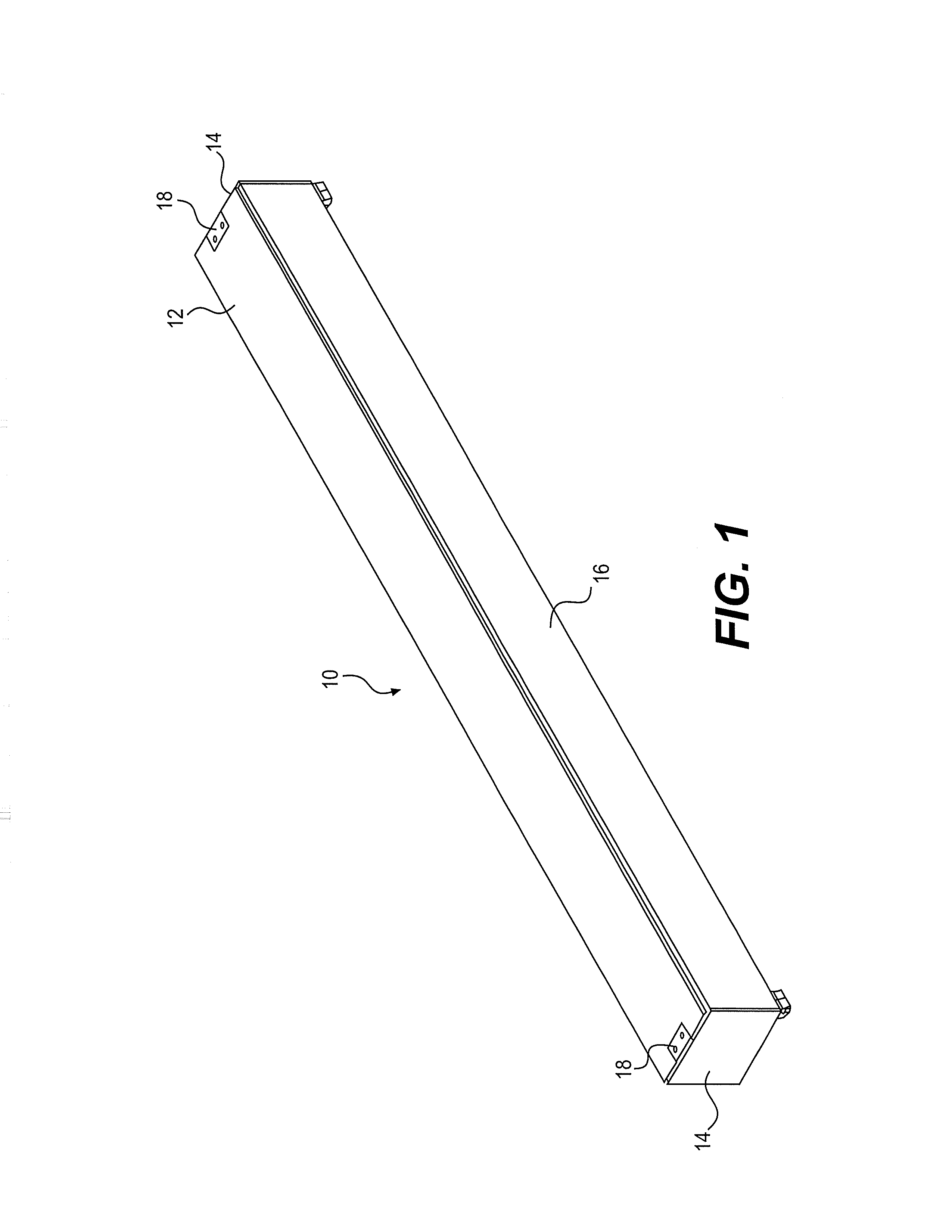
[0021]FIG. 1 illustrates a blind assembly 10 that may be used in accordance with some embodiments of the invention. The blind assembly 10 includes a header housing 12, end caps 14 and a cover 16. The end caps 14 may be attached to the header housing 12 via brackets 18. The cover 16 may be attached to the end caps 14 by brackets that are hidden in the view of FIG. 1 and contained within the blind assembly 10. In other embodiments of the invention, other types of brackets or other attaching means may be used to attach the header housing 12, end caps 14 and the cover 16.
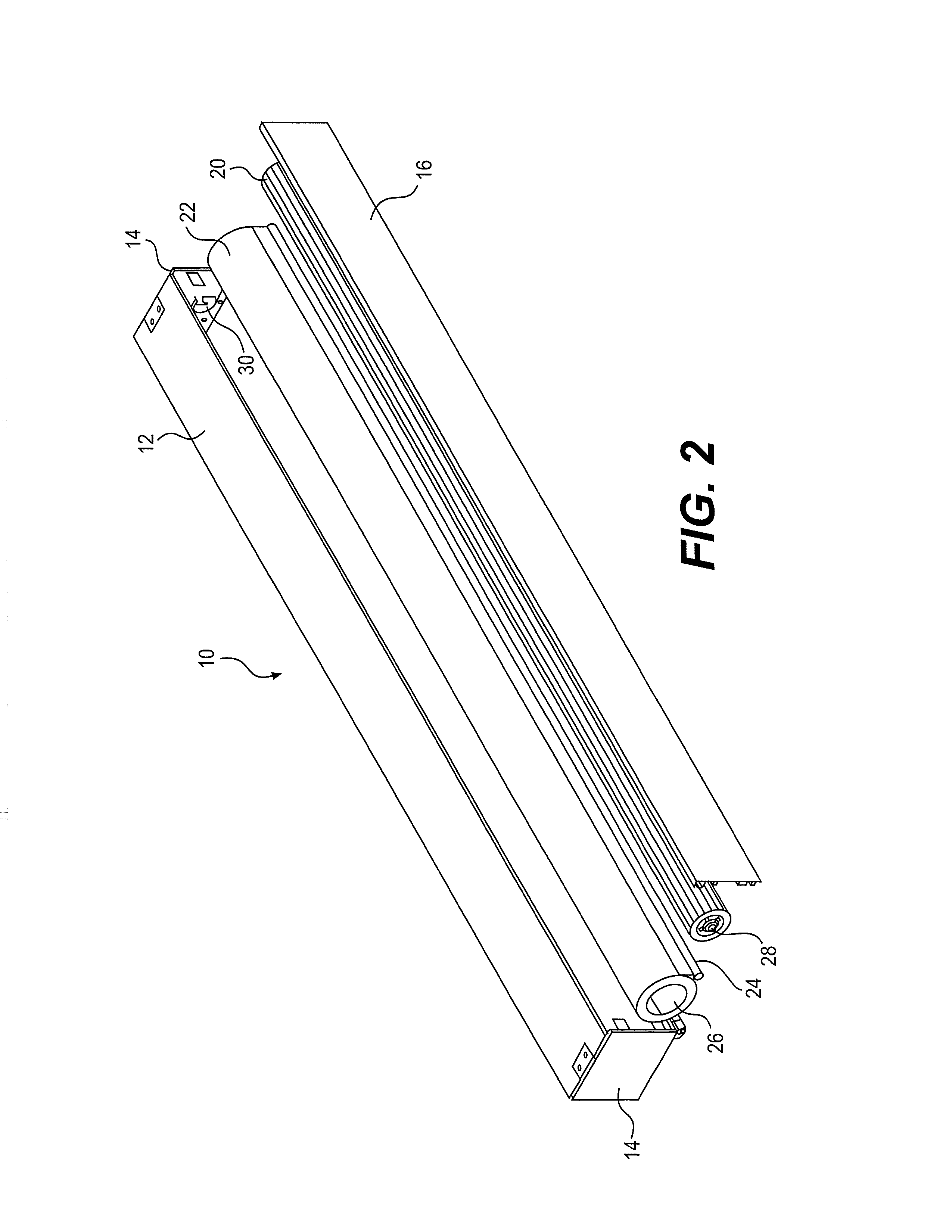
[0022]FIG. 2 is ...


PUM

PropertyMeasurementUnit
Weightaaaaaaaaaa
Thicknessaaaaaaaaaa

Abstract

A roller shade is provided. In some embodiments, the roller shade may include: a roller assembly; an inner portion of the roller assembly having an attaching structure for attaching to a mount; an outer portion of the roller assembly located on the roller assembly radially outward from the inner portion; a slot in the outer portion; and an insert dimensioned to be slidably received into the slot along with a portion of a shade to thereby attach the shade to the roller assembly. A method of attaching a shade to a roller assembly may also be provided.

Description

FIELD OF THE INVENTION[0001]The present invention relates generally to roller shades. More particularly, the present invention relates to an apparatus for attaching shade material to the roller assembly and counter balancing the roller assembly.BACKGROUND OF THE INVENTION[0002]Roller shades or blinds have long been used as window coverings. The roller shades may be mounted to the top of windows or above the windows. The window shades may be pulled down over the window to block out unwanted light and / or to provide privacy. Often the roller in the roller shade assembly is spring loaded and may have a pawl or similar system so that the roller shade can be pulled down and stopped at a desired position. In order to roll the shade back up, the shade is slightly pulled down by user to disengage the pawl. Then, the spring system turns the roller thereby rolling the shade or blind material around the roller as the shade or blind retracts. Like anything that rotates on an axis, it may be desi...

Claims


Application Information

Patent Timeline
IPC IPC(8): E06B9/44B23P11/00E06B9/50
CPCE04F10/0633Y10T29/49826E06B9/44E06B9/171
Inventor MULLET, WILLIS JAYBRUNK, DARRIN W.HAND, RICHARD SCOTTASBURY, HARRY EDWARD
Owner HOMERUN HLDG
Why Eureka
Try Eureka