Inflatable lamp assembly

a technology of inflatable lamps and lamps, which is applied in the field of inflatable lamps and assemblies, can solve the problems of inconvenient assembly or detachment, usually too big or too heavy to carry, and achieve the effect of convenient assembly and detachment and easy detachment of light emitting devices

Inactive Publication Date: 2013-07-25
CHIN HUAN CHIEN
View PDF29 Cites 28 Cited by
  • Summary
  • Abstract
  • Description
  • Claims
  • Application Information

AI Technical Summary

Benefits of technology

[0005]The present invention discloses an inflatable lamp assembly, which has several advantages of conveniently assembling and detaching, as well as easily detaching the light emitting apparatus from the bladder.

Problems solved by technology

However, these types of the lamp cover is usually too big or too heavy to carry.
However, it is quite inconvenient to assemble or detach.

Method used


Image

  • Inflatable lamp assembly
  • Inflatable lamp assembly
  • Inflatable lamp assembly

Examples


first embodiment

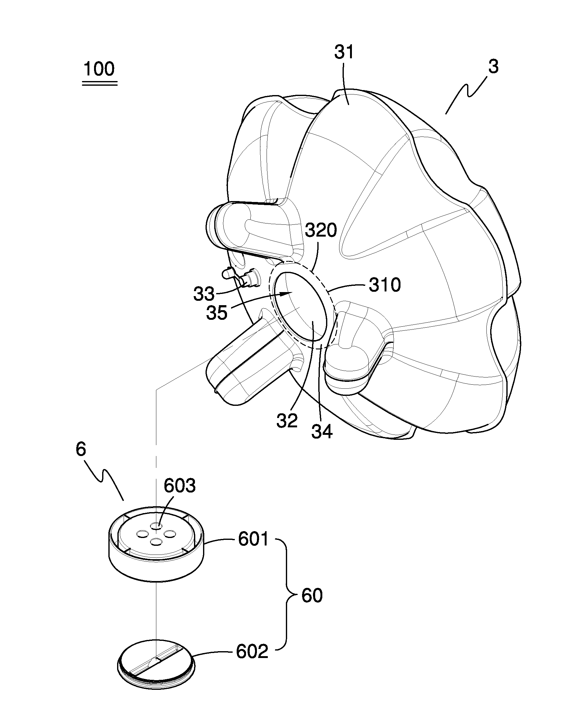
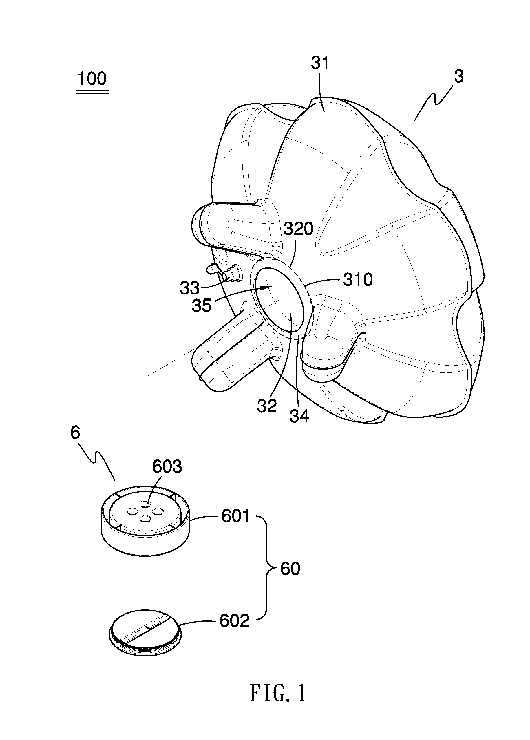
[0015]FIG. 1 to FIG. 3 are perspective drawings showing an inflatable lamp assembly (or called as a light floating assembly) according to the present invention. As shown in FIG. 1 to FIG. 3, the inflatable lamp assembly 100 comprises a bladder 3, a light emitting apparatus 6 disposed in the bladder 3 and a G-sensor (not shown).

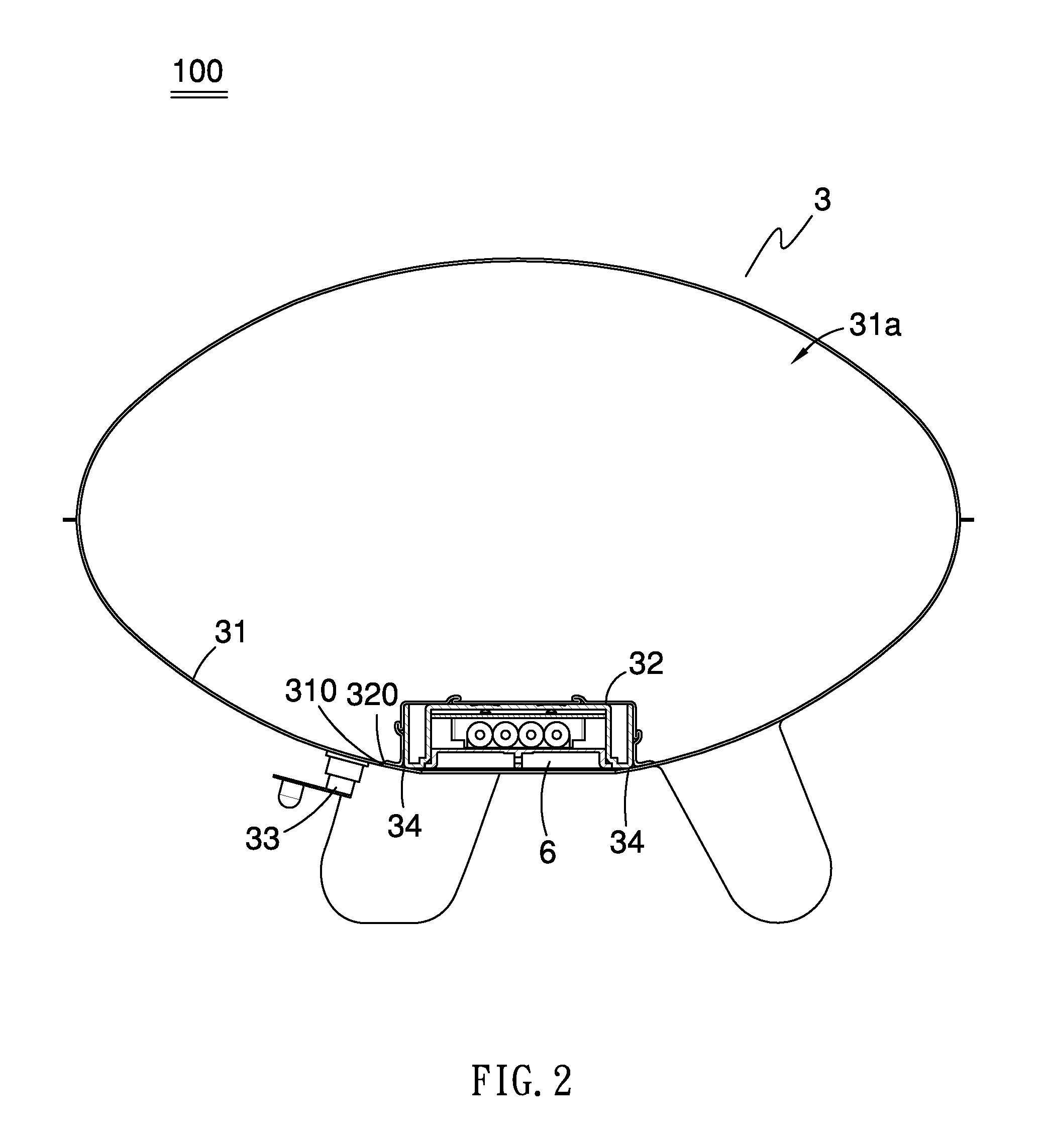
[0016]As shown in FIG. 2, the bladder 3 comprises a firs bag portion 31 (which is also named as outer bag portion), a second bag portion 32 (which is also named as inner bag portion) connected with the first bag portion 31 and an air nozzle 33. The first bag portion 31 and the second bag portion 32 are together formed an inflatable cell 31a for receiving air therein. The air nozzle 33 is disposed on the first bag portion 31 to provide inflate or deflate the inflatable cell 31a. Besides, the bladder 3 further comprises a flange 34 surrounding at periphery of an opening 320 of the second bag portion 32. The flange 34 is disposed at the opening 320 and faces the ...

second embodiment

[0021]FIG. 5 is a perspective drawing showing an inflatable lamp assembly 200 according to the present invention. Differences from the above mentioned embodiment includes that the light emitting apparatus 6 is reversely disposed in the recess. Which shows that the light emitting side of the light emitting apparatus 6, i.e. the side where the lens 603 positioned, faces outside of the bladder 3, and the light emitting apparatus 6 directly project light toward outside of the bladder 3, that does not project light toward inside of the bladder 3. This configuration can be applicable to a water lamp or an aquarium.


PUM

PropertyMeasurementUnit
brightnessaaaaaaaaaa
colorsaaaaaaaaaa
coloraaaaaaaaaa

Abstract

The present invention discloses an inflatable lamp assembly a bladder and a light emitting apparatus that assembled together. The bladder includes a first bag portion, a second bag portion connected with an opening of the first bag portion, an air nozzle disposed on the firs bag portion, and a flange disposed at the opening of the second bag portion. The first bag portion and the second bag portion are co-formed an inflatable cell which is capable of being inflated and deflated by the air nozzle. The light emitting apparatus is received in a recess defined between the second bag portion and flange. As such, the light emitting apparatus can be firmly clamped in the recess when the inflatable cell is filled with air.

Description

BACKGROUND OF INVENTION[0001]1. Field of Invention From one aspect, the invention relates to a lamp assembly, and more especially to an inflatable lamp assembly. From another aspect, the invention relates to a bladder, and more especially to a bladder that can be assembled with a light emitting apparatus.[0002]2. Related Prior Art[0003]A conventional lamp cover is made of a transparent material, such as acrylic resin or glass. However, these types of the lamp cover is usually too big or too heavy to carry.[0004]Taiwan Patent No. 69670 discloses an inflatable lamp cover that is easy to carry or to warehouse. The inflatable lamp further has a container melted with the bottom side of the lamp cover to accommodate a battery set therein for provide power to a lamp disposed in the lamp cover. The battery set is connected with the lamp cover by an embedded plate embedded in an opening of the container. However, it is quite inconvenient to assemble or detach.SUMMARY OF INVENTION[0005]The pr...

Claims


Application Information

Patent Timeline
Patent Type & Authority Applications(United States)
IPC IPC(8): H05B37/02F21V5/04B32B1/02F21V21/14
CPCF21S9/02F21V3/026F21V23/0492Y10T428/13F21Y2113/005F21V23/0485F21Y2101/02F21Y2115/10F21Y2113/13
Inventor CHIN-HUAN, CHIEN
Owner CHIN HUAN CHIEN
Why Eureka
Try Eureka