

Process for making nitriles
a technology of nitrile and process, which is applied in the preparation of carboxylic acid nitrile, organic compound preparation, carboxylic acid nitrile, etc., can solve the problems of loss of product yield and purity, waste of resources, etc., and achieve the effect of reducing the buildup of catalyst degradation products and reaction byproducts
- Summary
- Abstract
- Description
- Claims
- Application Information
AI Technical Summary
Benefits of technology
Problems solved by technology
Method used
Image

Examples
example 1
Operating Parameters and Results
[0371]Nickel dosage is maintained at about 500 ppm weight (based on total feed) in the first reaction zone (Z1). Ligand dosage is controlled at around 3:1 molar ratio of bidentate ligand:nickel.
[0372]Catalyst loss is observed when the bottoms (process side of the reboiler) operating temperature in the butadiene column (the first distillation column after the first reaction zone) exceeds about 125° C. While not to limit the scope of the invention by a recitation of theory, it is believed that the loss of the bidentate ligand component of the catalyst is due to thermal degradation. To maintain ligand inventory, the butadiene column bottoms (the first column after the first reaction zone) is controlled at 125° C. Initially, this results in an unacceptably high level of unreacted butadiene in the pentenenitrile-enriched bottoms product. In an attempt to solve this problem, the butadiene column is upgraded for vacuum operation, and refrigeration equipment ...
example 2
Segregated Catalyst Recovery Systems
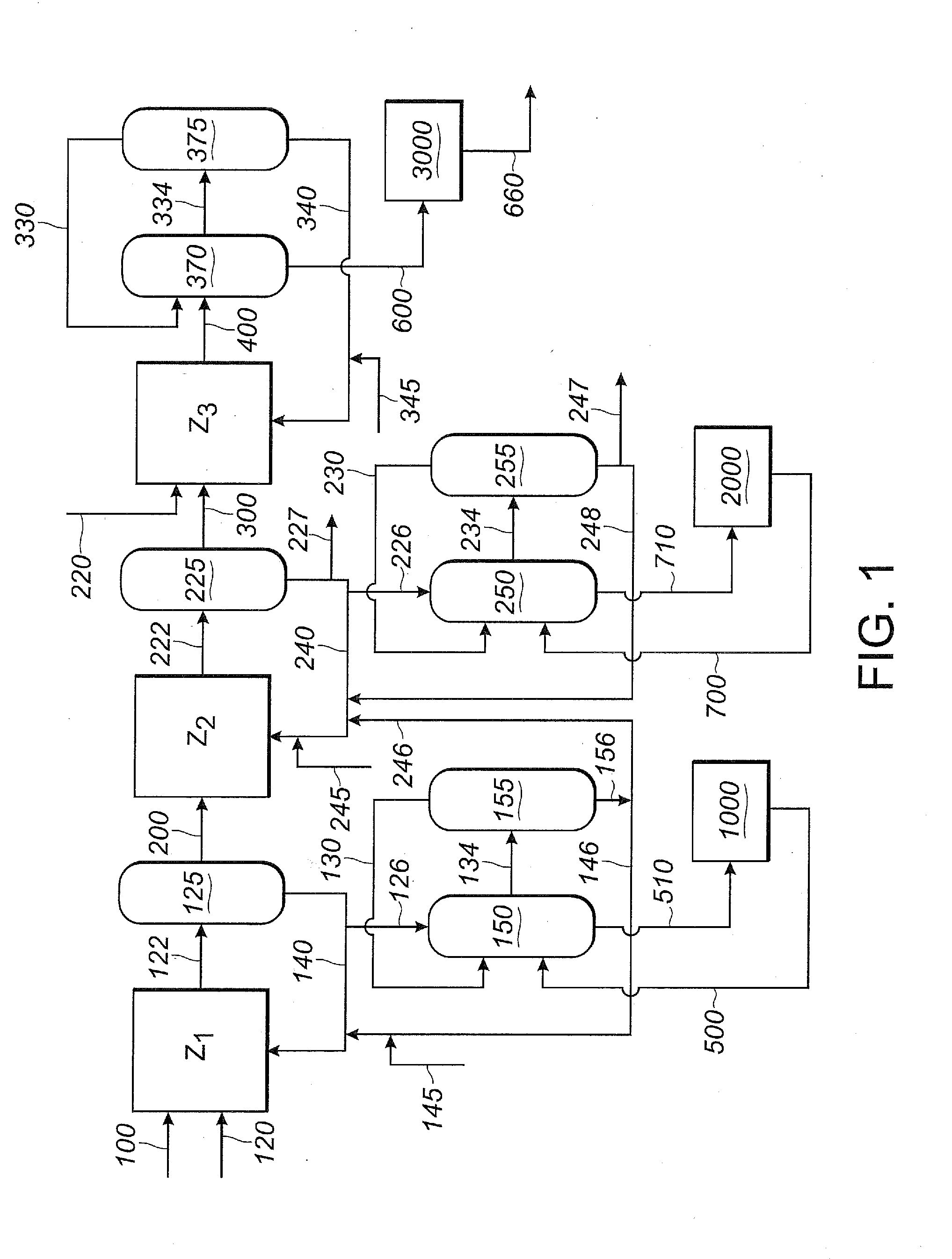
[0374]This Example 2 illustrates segregated catalyst recovery systems. In particular, this Example 2 illustrates a process using three separate catalyst recovery systems where each of reaction zones Z1, Z2 and Z3 contain catalyst comprising nickel and a bidentate phosphite-containing ligand having the structure of Formula III, above.
[0375]In this Example 2, as shown in FIG. 1, 1,3-butadiene reactant is fed into the first reaction zone (Z1) through line 100, hydrogen cyanide reactant is fed into the first reaction zone (Z1) through line 120, and catalyst is fed into the first reaction zone (Z1) through line 140. A reaction product stream is taken from the first reaction zone (Z1) through line 122. The reaction product stream in line 122 comprises products, byproducts, unreacted reactants and catalyst, which flows through the first reaction zone (Z1). The reaction product stream 122 is introduced into a separation section 125, to obtain, inter alia,...
example 3
Segregated Catalyst Recovery Systems
[0415]Example 3 illustrates partially segregated catalyst recovery systems with monodentate ligand in the Z1 / Z2 catalyst loops and bidentate ligand in the Z3 catalyst loop where the Z1 and Z2 catalyst loops share a first catalyst recovery section and the Z3 catalyst loop has a dedicated second catalyst recovery system. In this Example 3, the Z1 / Z2 catalyst recovery section and the Z3 catalyst recovery section are segregated to minimize flow of the monodentate ligand of Z1 / Z2 into the bidentate ligand of Z3, and the bidentate ligand and Lewis acid of Z3 into the monodentate ligand of Z1 / Z2.
[0416]For this Example 3, Example 2 is repeated, except that the first reaction zone (Z1) and the second reaction zone (Z2) share a single catalyst recovery system, not shown in FIG. 1. A shared catalyst recovery system may be desirable when the first and second phosphite-containing ligands are the same, as is the case in this Example 3, where both Z1 and Z2 use ...
PUM
| Property | Measurement | Unit |
|---|---|---|
| chemical yield | aaaaa | aaaaa |
| purity | aaaaa | aaaaa |
| concentration | aaaaa | aaaaa |
Abstract
Description
Claims
Application Information