Footwear Having Sensor System

a sensor system and footwear technology, applied in the field of footwear having a sensor system, can solve the problems of complex sensor system, data cannot be accessed or used, unnecessarily limited use of collected data, and have certain limitations

Inactive Publication Date: 2013-08-22
NIKE INC +1
View PDF8 Cites 225 Cited by
  • Summary
  • Abstract
  • Description
  • Claims
  • Application Information

AI Technical Summary

Benefits of technology

[0008]According to another aspect, the spacer layer may include a first hole aligned with one of the sensors to permit at least partial engagement between the first and second contacts of the sensor through the spacer layer, and may further include a channel extending from the hole to a vent in the insert member, wherein the channel permits air to flow between the first and second layers from the sensor to an exterior of the insert member, through the first vent. The vent may have a selectively permeable closure member positioned to cover the vent. Additionally, the vent may be connected to more than one sensor through additional channels, and / or the insert may contain a second vent connected to one or more sensors in a similar arrangement. An article of footwear incorporating the insert may include a cavity within a sole member of the footwear that is located at least partially below the vent. The cavity extends laterally from the vent to a distal end located outside a peripheral boundary of the insert, such that the cavity is configured to permit the air exiting the first vent to pass away from the insert member. Further, a patch of dielectric material may be connected to one of the first and second layers and may extend across the channel to be positioned between the first and second layers, resisting shorting of one or more conductive members between the first and second layers through the channel.
[0009]According to a further aspect, the insert may include an extension extending into the well and consolidating the ends of the leads to form the interface, the extension having a strip of reinforcing material extending across the ends of the leads. The extension has a bend area where the extension bends downwardly at or near a peripheral edge of the housing and a depending portion that extends downwardly from the bend area into the well. In this configuration, the interface is located on the depending portion within the well, and the strip extends transversely across the bend area to provide reinforcement and wear resistance to the bend area. The system may also contain an interface assembly that includes a base member and a plurality of electrical connectors supported by the base member, where at least a portion of the depending portion is received in the base member and the ends of the leads engage the electrical connectors to form the interface.

Problems solved by technology

In certain systems, the sensor systems are complex or data can only be accessed or used with certain operating systems.
Thus, uses for the collected data can be unnecessarily limited.
Accordingly, while certain shoes having sensor systems provide a number of advantageous features, they nevertheless have certain limitations.

Method used


Image

  • Footwear Having Sensor System
  • Footwear Having Sensor System
  • Footwear Having Sensor System

Examples


Embodiment Construction

[0093]While this invention is susceptible of embodiment in many different forms, there are shown in the drawings, and will herein be described in detail, preferred embodiments of the invention with the understanding that the present disclosure is to be considered as an exemplification of the principles of the invention and is not intended to limit the broad aspects of the invention to the embodiments illustrated and described.

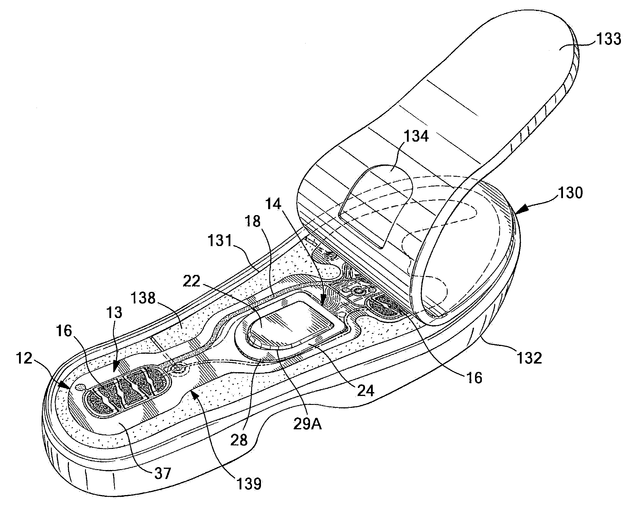
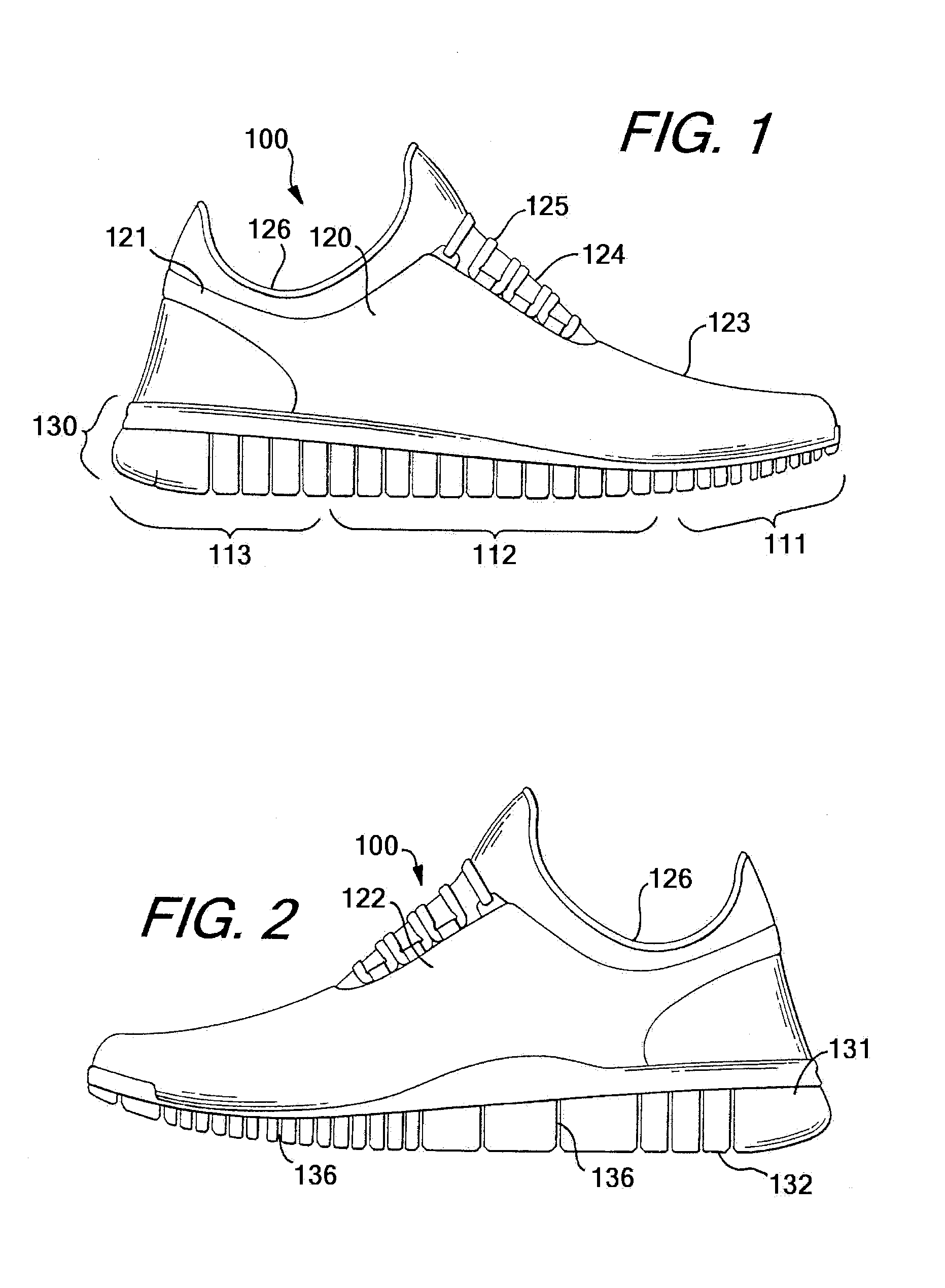
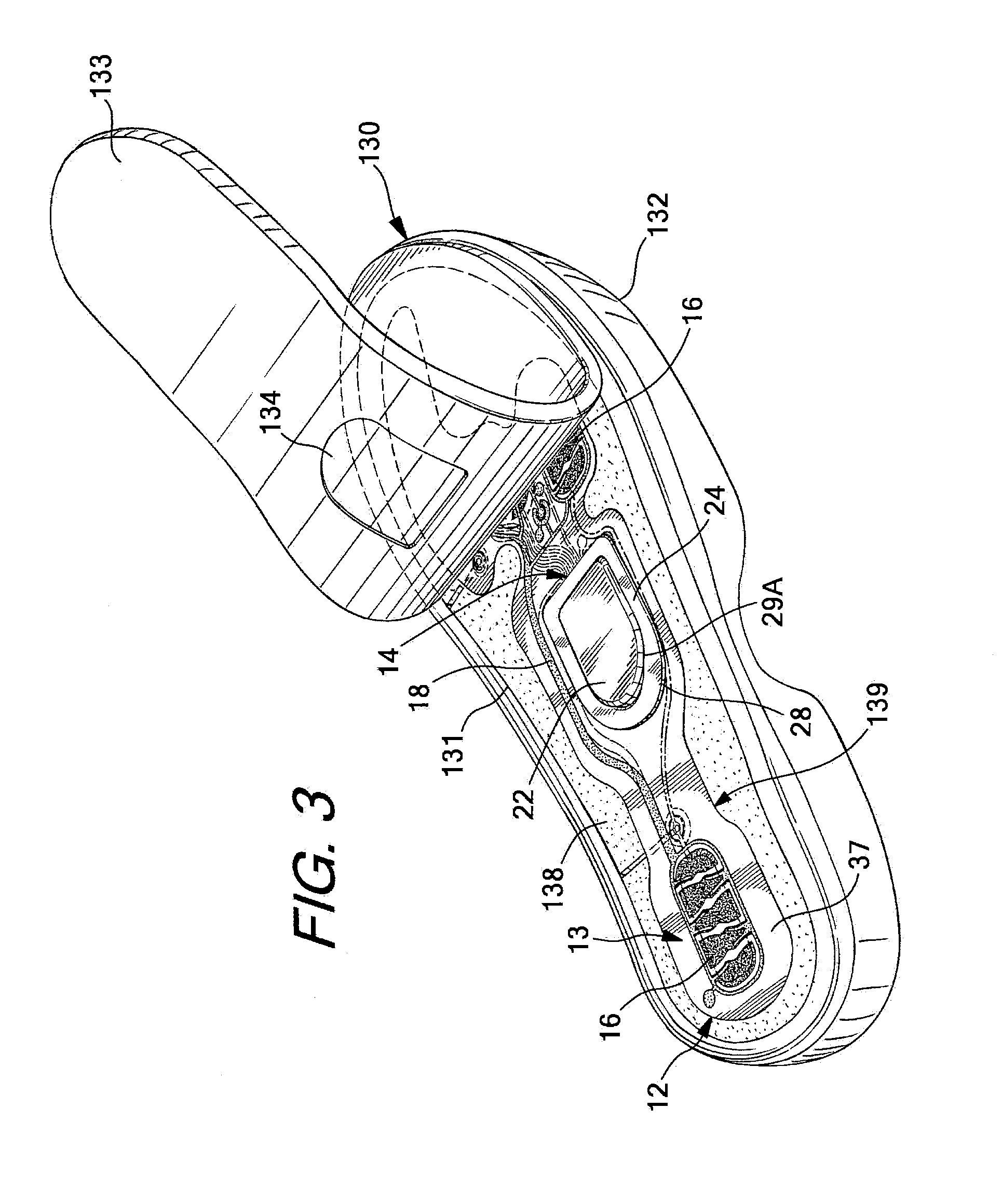
[0094]Footwear, such as a shoe, is shown as an example in FIGS. 1-2 and generally designated with the reference numeral 100. The footwear 100 can take many different forms, including, for example, various types of athletic footwear. In one exemplary embodiment, the shoe 100 generally includes a force and / or pressure sensor system 12 operably connected to a universal communication port 14. As described in greater detail below, the sensor system 12 collects performance data relating to a wearer of the shoe 100. Through connection to the universal communication po...


PUM

PropertyMeasurementUnit
depthaaaaaaaaaa
thicknessaaaaaaaaaa
thicknessaaaaaaaaaa

Abstract

A sensor system is adapted for use with an article of footwear and includes an insert member including a first layer and a second layer, a port connected to the insert and configured for communication with an electronic module, a plurality of force and / or pressure sensors on the insert member, and a plurality of leads connecting the sensors to the port.

Description

TECHNICAL FIELD[0001]The present invention generally relates to footwear having a sensor system and, more particularly, to a shoe having a force and / or pressure sensor assembly operably connected to a communication port located in the shoe.BACKGROUND[0002]Shoes having sensor systems incorporated therein are known. Sensor systems collect performance data wherein the data can be accessed for later use such as for analysis purposes. In certain systems, the sensor systems are complex or data can only be accessed or used with certain operating systems. Thus, uses for the collected data can be unnecessarily limited. Accordingly, while certain shoes having sensor systems provide a number of advantageous features, they nevertheless have certain limitations. The present invention seeks to overcome certain of these limitations and other drawbacks of the prior art, and to provide new features not heretofore available.BRIEF SUMMARY[0003]The present invention relates generally to footwear having...

Claims


Application Information

Patent Timeline
Patent Type & Authority Applications(United States)
IPC IPC(8): G01L1/20
CPCG01L1/20A43B13/386A61B5/1114A61B5/112A61B5/1121A61B5/1124A61B5/6807A61B2503/10A61B2560/045A61B2562/0247A61B2562/0252A61B2562/046A61B2562/164A61B2562/166A61B2562/168A61B2562/222A61B2562/227G01L1/205A43B3/0005A43B7/084A43B7/088A43B13/12A43B13/14A43B13/203A61B5/0022A43B3/34
Inventor RICE, JORDAN M.SCHROCK, ALLAN M.WALKER, STEVEN H.ATANG, NDIKUM PROTUSSTEIER, ANDREAS HEINRICHCUMMINGS, KATE
Owner NIKE INC
Why Eureka
Try Eureka