
Apparatus and methods for mounting a photovoltaic module on a roof

Active Publication Date: 2013-08-29
JOHNS MANVILLE CORP
View PDF5 Cites 17 Cited by
  • Summary
  • Abstract
  • Description
  • Claims
  • Application Information

AI Technical Summary

Benefits of technology

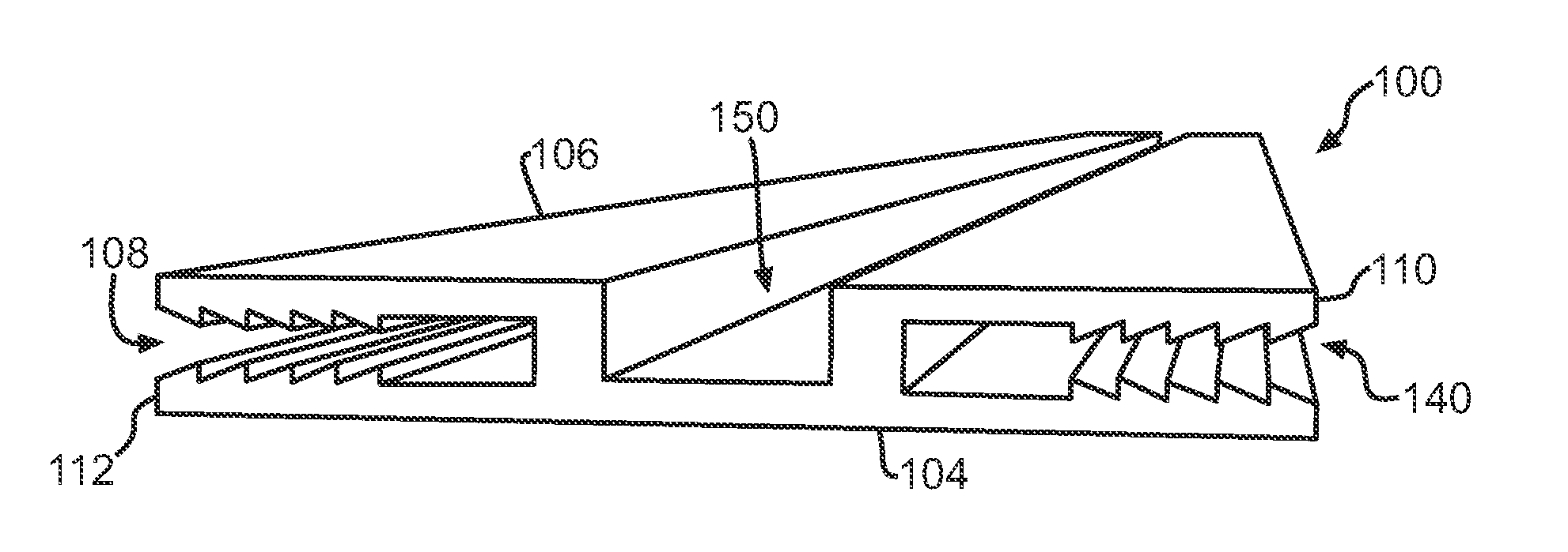
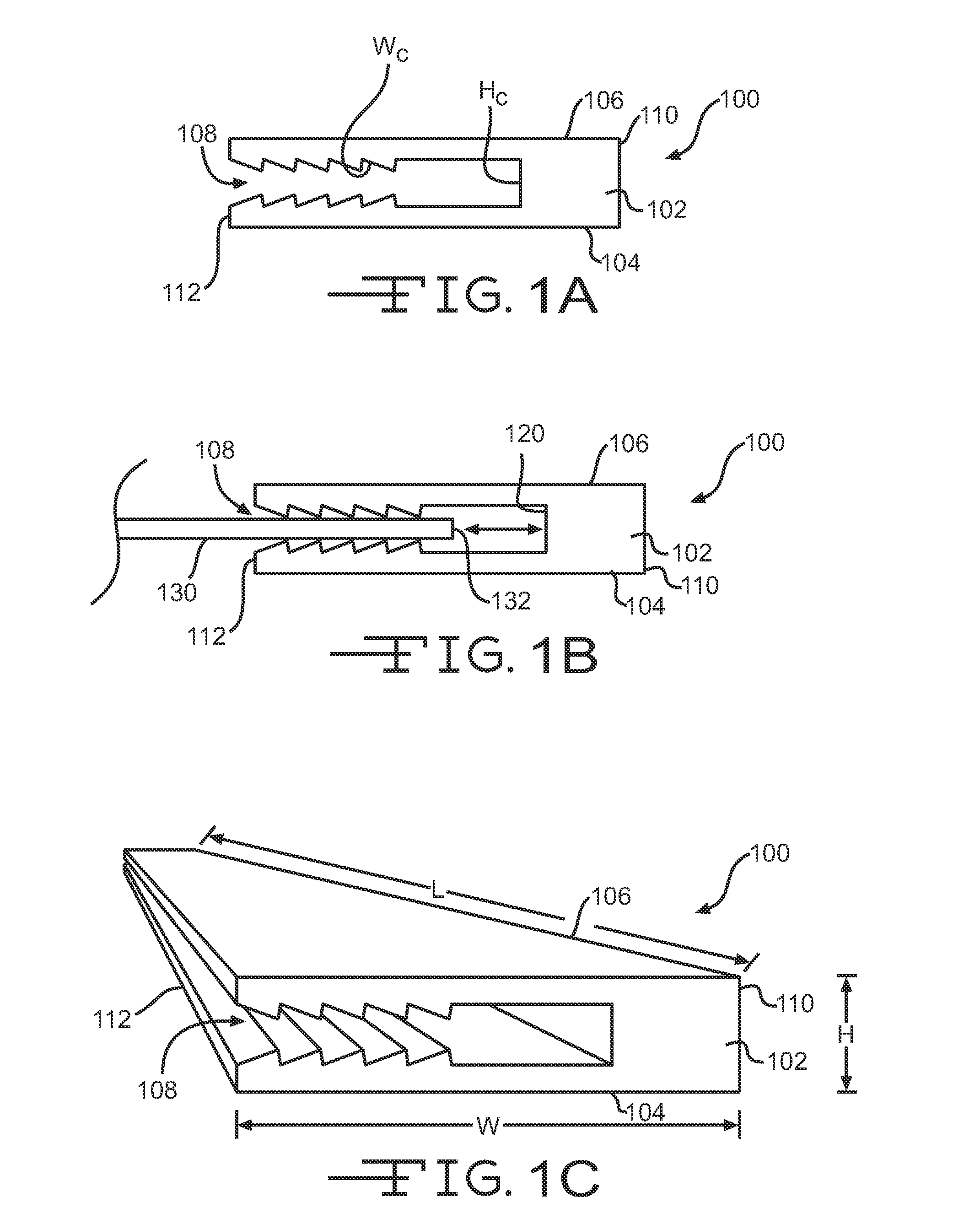
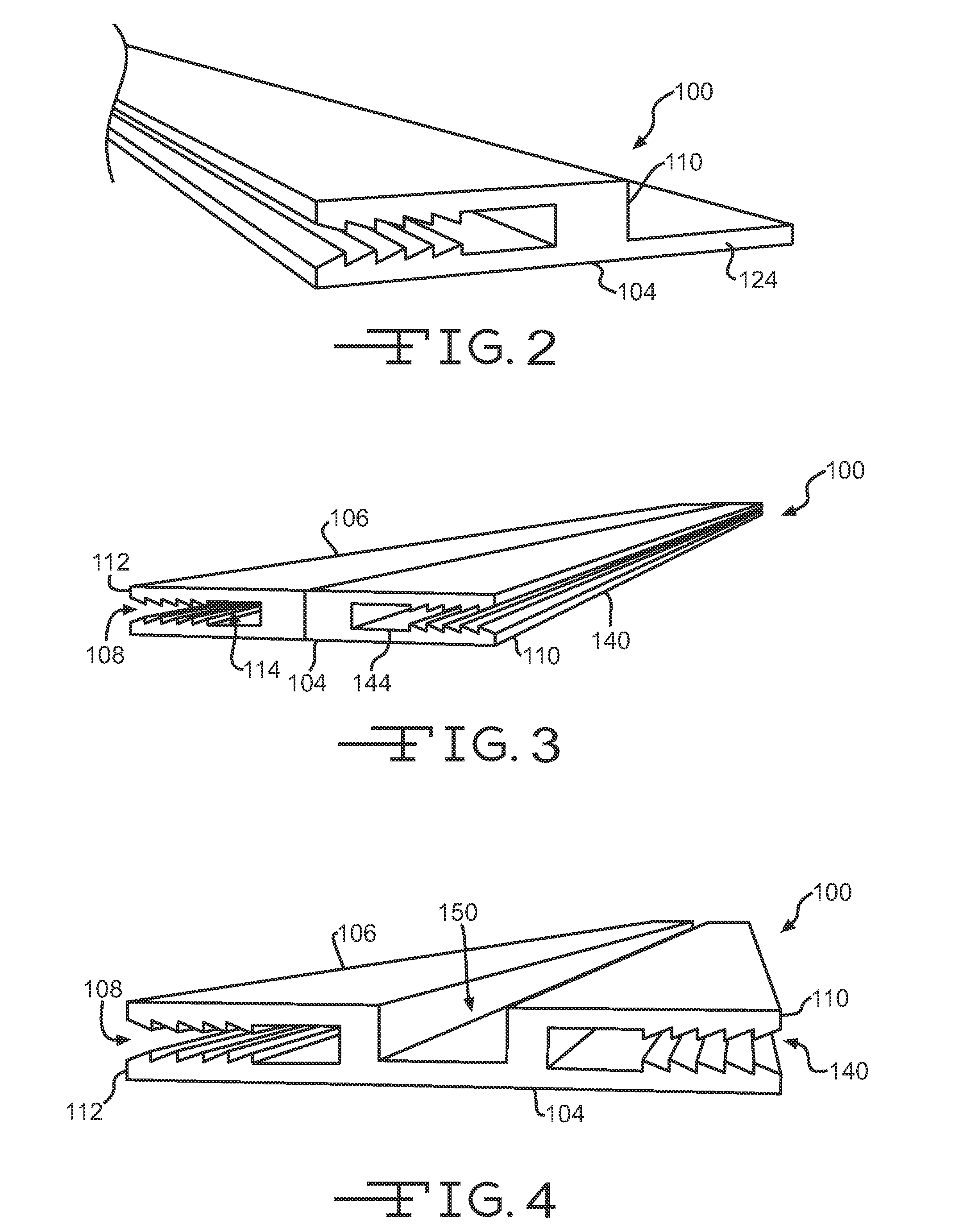
The invention provides a system for mounting a photovoltaic module to a structure, such as a roof, that includes a first mounting device and a second mounting device. The first mounting device has a mounting channel with a top surface, a bottom surface, and a longitudinal edge. The first mounting device also has a recessed channel that allows the photovoltaic module to expand or contract within the mounting channel. The second mounting device has a mounting channel that faces the mounting channel of the first mounting device. The system also includes a photovoltaic module that can be inserted into the mounting channels of the first and second mounting devices. The invention provides a simple and effective way to mount photovoltaic modules to structures.

Problems solved by technology

Mechanically fastening the photovoltaic modules to the roof often produces holes through the photovoltaic modules and / or roof surface, which may compromise the performance of the photovoltaic modules and / or allow water of other fluids to penetrate through the roof or underneath the photovoltaic module.
Adhesively bonding the photovoltaic modules to the roof's surface often permanently attaches the photovoltaic module to the roof's surface so that the photovoltaic module is not removable without damaging the roof's surface.
Further, an installer must carefully place and properly align adhesively bonded photovoltaic modules on the roof's surface since the adhesives suitable for this purpose often aggressively bond with virtually any surface they contact.
In addition, mechanically fastened and adhesively bonded photovoltaic modules often transfer stress to or receive stress from the roof's surface as the roof and photovoltaic modules expand and contract due to shifts in temperature and the like.

Method used


Image

  • Apparatus and methods for mounting a photovoltaic module on a roof
  • Apparatus and methods for mounting a photovoltaic module on a roof
  • Apparatus and methods for mounting a photovoltaic module on a roof

Examples


Embodiment Construction

[0021]The ensuing description provides exemplary embodiments only, and is not intended to limit the scope, applicability or configuration of the disclosure. Rather, the ensuing description of the embodiments will provide those skilled in the art with an enabling description for implementing one or more embodiments. It being understood that various changes may be made in the function and arrangement of elements without departing from the spirit and scope of the invention as set forth in the appended claims.

[0022]Also, it is noted that individual embodiments may be described as a process which is depicted as a flowchart, flow diagram, or block diagram. Although a flowchart may describe the operations as a sequential process, many of the operations can be performed in parallel or concurrently. In addition, the order of the operations may be re-arranged. A process may be terminated when its operations are completed, but could have additional steps not discussed or included in a figure. ...


PUM


Abstract

Embodiments of the invention provide systems, devices, and methods for mounting a photovoltaic module to a structure, such as a roof. An embodiment of a method for mounting a photovoltaic module to a structure may include providing a photovoltaic module, a first mounting device, and a second mounting device. The first mounting device and the second mounting device may be coupled with the structure, such as a roofing membrane, so that opposing mounting channels of the respective devices face one another. The method may further include inserting a first edge of the photovoltaic module within the mounting channel of the first mounting device and inserting a second edge of the photovoltaic module within the mounting channel of the second mounting device so that the photovoltaic module is disposed between the first mounting device and the second mounting device.

Description

BACKGROUND OF THE INVENTION[0001]This invention relates generally to attaching photovoltaic modules to a structure, such as a roof of a building. More specifically the invention relates to mounts for attaching photovoltaic modules to such structures.[0002]Photovoltaic modules or panels are often positioned on the roof of a structure or building to convert solar energy to electrical energy in order to operate various equipment, machinery, lighting or other fixtures, and the like. Some photovoltaic modules (e.g., flexible photovoltaic modules) may be held in place atop the roof by adhesively bonding the photovoltaic modules to the roof's surface or mechanically fastening the photovoltaic modules directly to the roof's surface. Mechanically fastening the photovoltaic modules to the roof often produces holes through the photovoltaic modules and / or roof surface, which may compromise the performance of the photovoltaic modules and / or allow water of other fluids to penetrate through the ro...

Claims


Application Information

Patent Timeline
IPC IPC(8): H01L31/045H01L31/042F16B17/00H01L31/18H02S30/20
CPCY02B10/12F24J2/5205F24J2/5207F24J2002/4672F24J2002/4692Y10T403/45Y02B10/20Y02E10/47Y10T29/49355Y10T403/70H02S20/23F24S25/33F24S25/35F24S2025/6008F24S2080/015Y02B10/10Y02E10/50
Inventor BABINEAU, JR., FRANCIS JOHNMCGRAW, ETHAN NELSONASEERE, LESTER MICKEL
Owner JOHNS MANVILLE CORP
Learn More