Textile covering incorporating an optical fibre and associated installation method

a technology of textile coverings and optical fibres, which is applied in the installation of optical fibres, domestic applications, lighting and heating apparatus, etc., can solve the problems of difficulty in holding the ends of optical fibres in an upright position in the middle of textile coverings, and achieve the effect of improving the holding position of ends

Active Publication Date: 2013-10-10
AIRBUS JET CENT
View PDF5 Cites 3 Cited by
  • Summary
  • Abstract
  • Description
  • Claims
  • Application Information

AI Technical Summary

Benefits of technology

[0010]The purpose of the present invention is to propose a textile covering incorporating an optical fibre and a method for installing optical fibres in a textile covering improving the holding in position of the ends of the optical fibres in the textile covering.

Problems solved by technology

It is however difficult to hold the ends of the optical fibres in an upright position in the middle of the textile fibres, and for example in a vertical position when the textile covering is laid on the floor, even when the covering has relatively dense tufts of textile fibres.

Method used


Image

  • Textile covering incorporating an optical fibre and associated installation method
  • Textile covering incorporating an optical fibre and associated installation method
  • Textile covering incorporating an optical fibre and associated installation method

Examples


Embodiment Construction

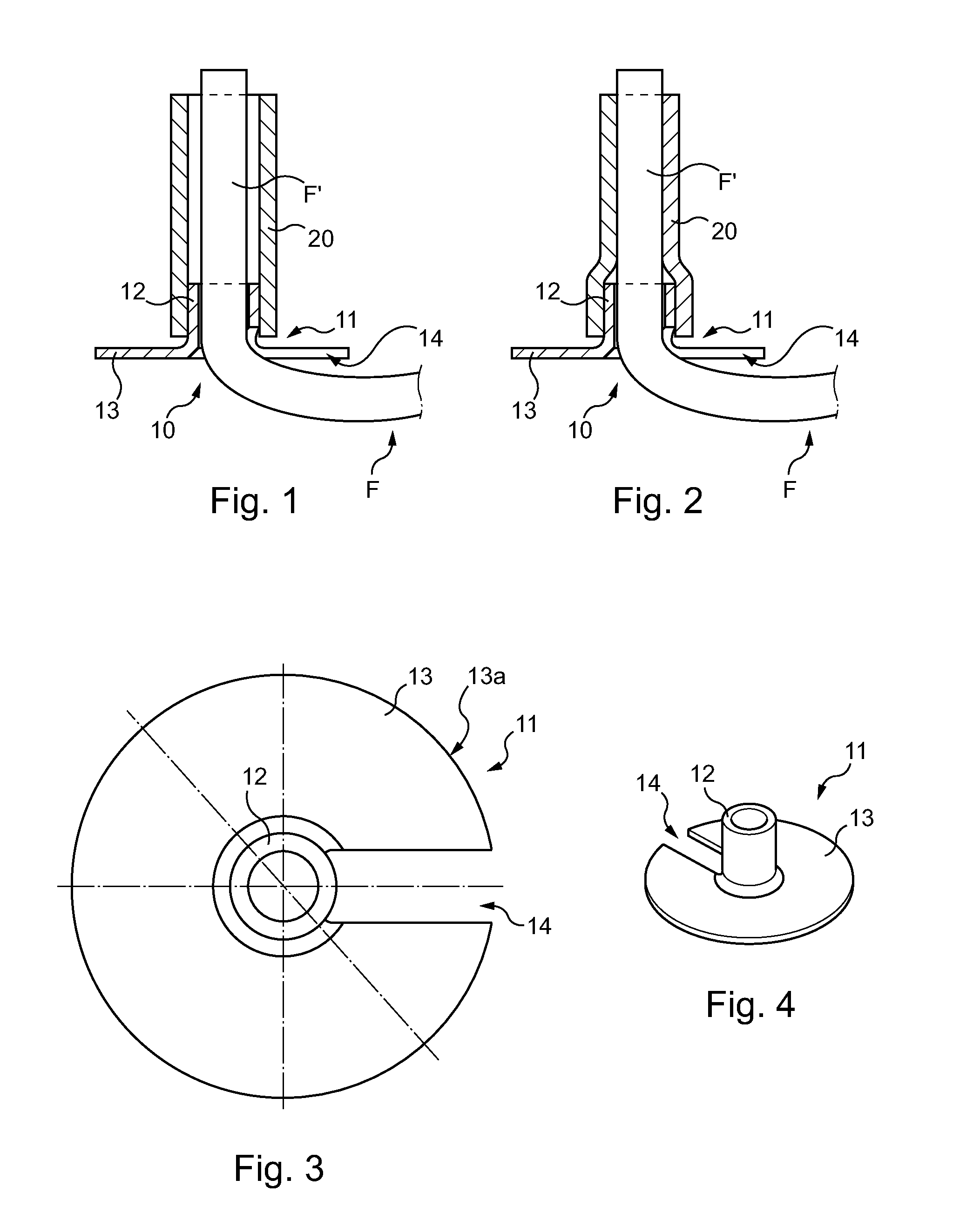
[0051]First, with reference to FIGS. 1 and 2 a support device of an optical fibre intended to hold an end portion of an optical fibre in a textile covering, and in particular in a carpet intended to cover a wall, will be described.

[0052]In the remainder of the description, it will be assumed non-limitatively that the support device of an optical fibre is intended to hold vertical an end of optical fibre in a carpet laid on the floor.

[0053]The support device 10 comprises a fixing ring 11 intended to be fixed on an optical fibre F.

[0054]In this embodiment, the fixing ring 11 comprises a cylindrical portion 12 the internal diameter of which is substantially equal to the external diameter of the optical fibre F.

[0055]Thus, the optical fibre F can be inserted inside the cylindrical portion 12 of the fixing ring 11.

[0056]The fixing ring 11 also comprises a base 13. This base 13 thus forms a collar at one end of the cylindrical portion 12 of the fixing ring 11.

[0057]A cut-out 14 is provide...


PUM

PropertyMeasurementUnit
internal diameteraaaaaaaaaa
diameteraaaaaaaaaa

Abstract

A textile covering, comprising an under-layer in contact with a rear face of a layer of textile fibres, and comprising an optical fibre housed inside a routing groove in the under-layer, an end portion of the optical fibre extending through the layer of textile fibres via a support device of the optical fibre. The support device comprises a fixing ring and a heat-shrink tubing covering part of the fixing ring and of the end portion. The fixing ring comprises a base in contact with the rear face and a cylindrical portion into which the end portion of the optical fibre is inserted. The textile covering may be used as carpet equipping the floor of an aircraft cabin.

Description

CROSS-REFERENCES TO RELATED APPLICATIONS[0001]This application claims the benefit of the French patent application No. 1253229 filed on Apr. 6, 2012, the entire disclosures of which are incorporated herein by way of reference.BACKGROUND OF THE INVENTION[0002]The present invention relates to a textile covering incorporating an optical fibre.[0003]It also relates to a method for installing optical fibres in a textile covering.[0004]The present invention generally relates to the field of the installation of optical fibres in a carpet-type textile covering, making it possible to obtain a lighting pattern on the floor.[0005]In particular it is used, non-limitatively, for the interior furnishing of an aircraft cabin.[0006]In this type of use, provision can be made for producing a covering with a pattern of light for aesthetic reasons but also for safety reasons, by providing for example a light guiding system on the floor.[0007]Thus, from the document U.S. Pat. No. 4,754,372 a textile cov...

Claims


Application Information

Patent Timeline
Patent Type & Authority Applications(United States)
IPC IPC(8): F21V33/00B23P19/00D06C27/00
CPCB23P19/00D06C27/00F21V33/0028B60Q3/0256Y10T29/49865B60Q3/004B60Q3/0283B60Q2500/10G02B6/0008B60Q3/64B60Q3/46B60Q3/745B60Q3/54B60N3/042
Inventor DESTIEU, JEAN-CYRILLESERVANT, DORINENICOLAS, CYRILLEJAMME, ISABELLE
Owner AIRBUS JET CENT
Why Eureka
Try Eureka