

Mobile device case having tension elements
a mobile device and case body technology, applied in the field of protective mobile device cases, can solve the problems of lack of internal kinetic energy, damage to mobile electronic devices, lack of compact and sufficient structure or mechanism within the case to absorb at least a portion,
- Summary
- Abstract
- Description
- Claims
- Application Information
AI Technical Summary
Benefits of technology
Problems solved by technology
Method used
Image

Examples
Embodiment Construction
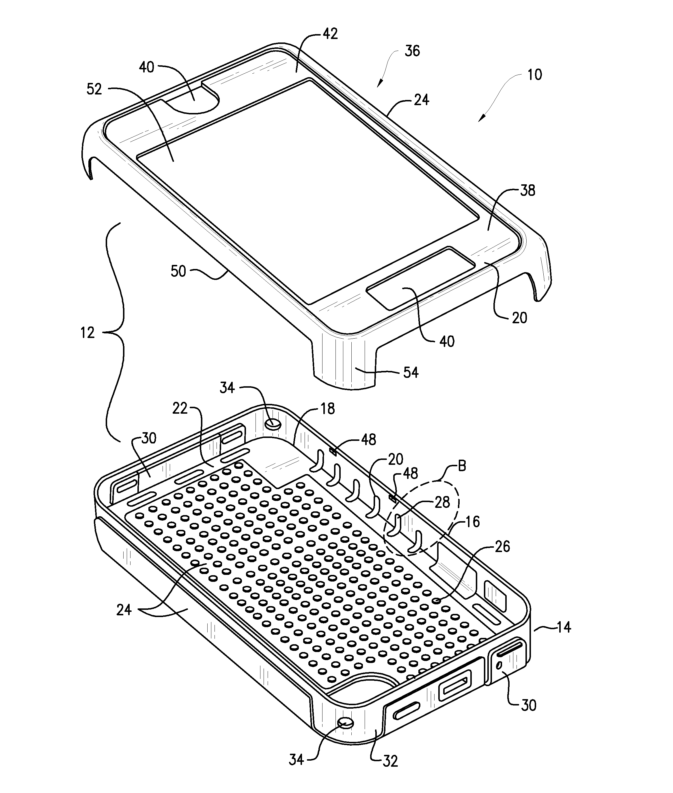
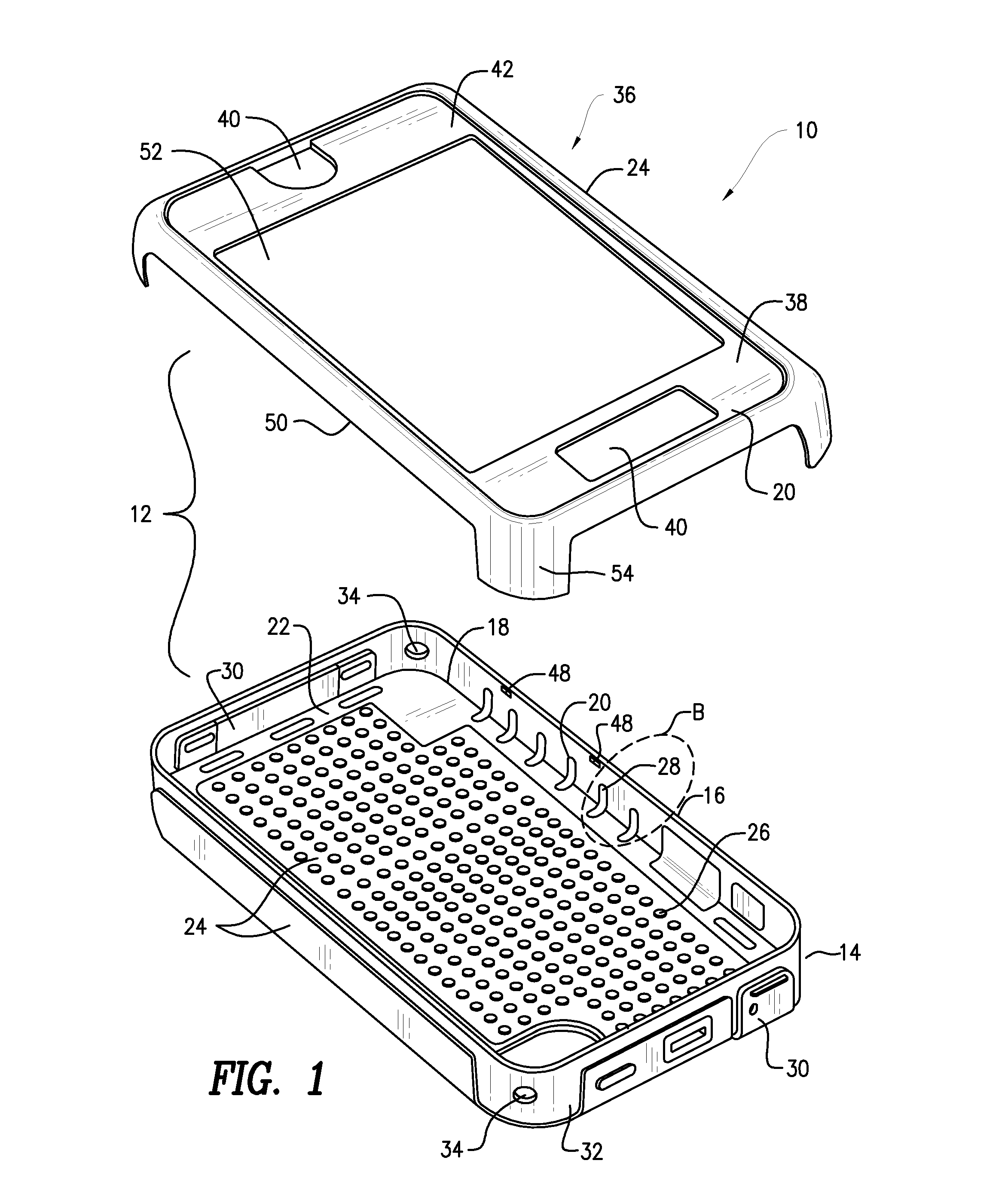
[0023]Now referring to the drawings in which like reference designators refer to like elements, there is shown in FIG. 1 a mobile device case constructed in accordance with the principles of the present invention and designated generally as “10.” The case 10 may include a housing 12 may be a multi-piece clam shell or a unitary structure sized to receive and retain a mobile device. The housing 12 may include a first portion 14 sized to receive and at least partially enclose the mobile device. For example, the dimensions of the first portion 14 may be pre-fabricated to contour a specific mobile device, for example an IPHONE, IPAD, or other mobile phone or tablet computer, and thus may vary depending on the size of the mobile device.
[0024]The first portion 14 may further include a plurality of side wall portions 16 defining a first perimeter 18 around the interior of the first portion 14. The side wall portions 16 surround the first portion 14 and may define a height substantially comm...
PUM
 Abstract
Description
Claims
Application Information