
Insert ring for spline coupling

Active Publication Date: 2013-12-26
PRATT & WHITNEY CANADA CORP
View PDF2 Cites 12 Cited by
  • Summary
  • Abstract
  • Description
  • Claims
  • Application Information

AI Technical Summary

Benefits of technology

The patent describes an insert ring for a spline coupling that includes U-shaped segments that fit into the keyways of a male spline. Each U-shaped segment has side walls that fit against the keyway surface and a gap that leaves a portion of the keyway exposed. The U-shaped segments are connected to each other by a distal end wall, leaving a portion of the spline tooth exposed between them. This design allows for a secure and reliable coupling between the male and female splines. The technical effect of this invention is to provide a more robust and reliable connection between splines.

Problems solved by technology

This increase in shaft size may also result in an increase in the size of the shaft seal, resulting in higher seal rubbing speeds, making the seals prone to leakage.

Method used


Image

  • Insert ring for spline coupling
  • Insert ring for spline coupling
  • Insert ring for spline coupling

Examples


Embodiment Construction

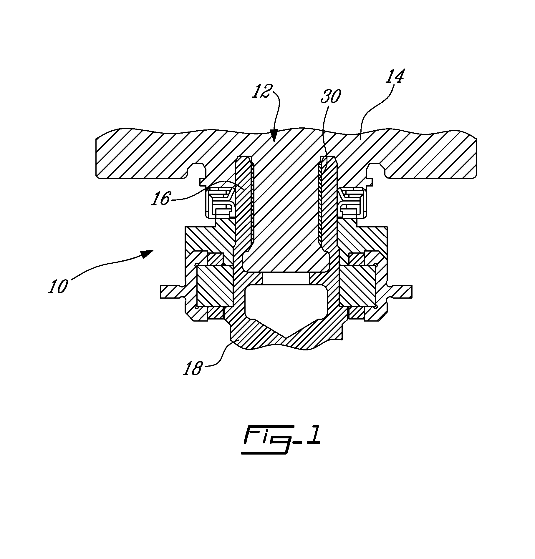
[0014]Referring to FIG. 1, there is illustrated a spline coupling 10 between a male spline 12 of a drive shaft 14, and a female spline 16 of a gearbox 18. The gearbox 18 may be used in gas turbine engines of aircraft and like vehicles. The male spline 12 may also be referred to as an external spline, while the female spline 16 may be referred to as an internal spline. Although the male spline 12 is illustrated as being on the driven end of the drive shaft 14, the male spline 12 could be on the driving end of the spline coupling 10.

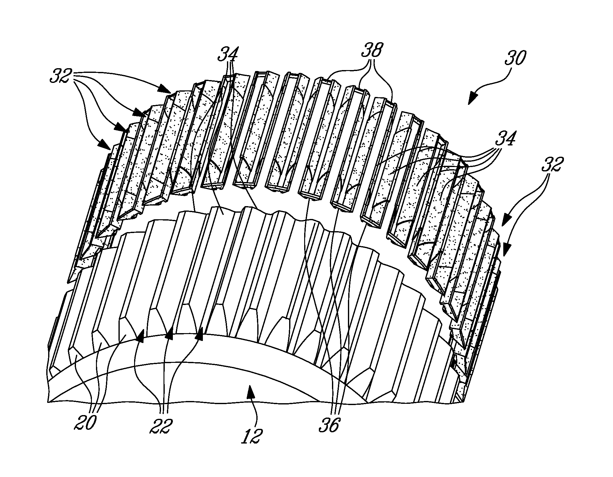
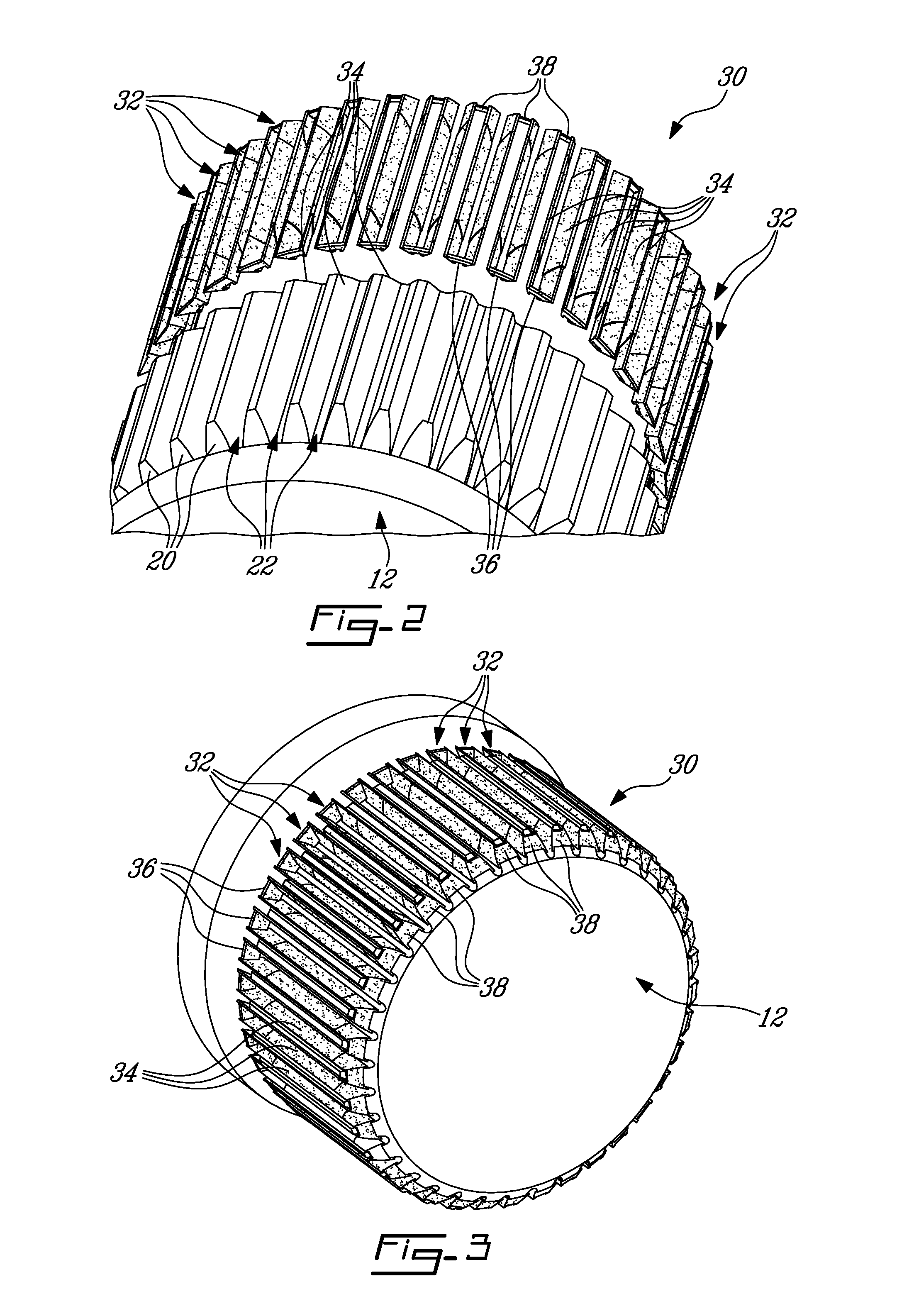
[0015]Referring concurrently to FIGS. 2 to 4, the male spline 12 has a plurality of spline teeth 20. The spline teeth 20 extend in an axial direction of the spline coupling and are generally equidistantly spaced apart from one another, on a circumference of the male spline 12. The teeth 20 are separated by keyways 22. There may be more or fewer of the teeth 20 and hence keyways 22 on the male spline 12, than what is shown in the illustrated embodiments. In...


PUM


Abstract

A spline coupling comprises a male spline having a plurality of spline teeth separated by keyways. An insert ring comprises a plurality of U-shaped segments each having a pair of side walls separated by a gap and interconnected by a proximal end wall. Each U-shaped segment is configured to be received in one of the keyways of the male spline with the side walls being against surfaces of the keyway and the gap leaving a portion of the keyway exposed. Each U-shaped segment is connected to adjacent U-shaped segments by a distal end wall to leave a portion of the spline teeth exposed between each pair of adjacent U-shaped segments. A female spline has a shape complementary to that of a combination of the male spline and insert ring for coupling engagement therebetween.

Description

TECHNICAL FIELD[0001]The application generally relates to spline couplings of the type used between gearboxes and shafts, and more particularly to an insert ring used as an interface between male and female couplings.BACKGROUND ART[0002]As the drive splines of gearbox gears tend to wear, several different methods are used to minimize this wear. The splines can be case-hardened steel, and either lubricated by a continuous flow of oil or packed with grease. The other system used is a non-lubricated “plastic” spline coupling insert, as an intermediate piece, that is splined on both its inner and outer diameters. This insert fits between the steel splines of the accessory gearbox drive and the spline on the accessory shaft itself.[0003]The plastic spline coupling insert, while not requiring any lubrication, may increase the size of not only the gearbox shaft, but also the bearing that is supporting the end of the shaft. Additionally, the housing also grows in size to accommodate the bea...

Claims


Application Information

Patent Timeline
IPC IPC(8): F16B7/00
CPCF16D1/101F16D2001/103Y10T403/7026
Inventor KENAWY, SEHAMBRAND, JOSEPH H.KOSTKA, RICHARD
Owner PRATT & WHITNEY CANADA CORP
Learn More