Robotic device movable in three mutually perpendicular directions

a robot and mutually perpendicular technology, applied in the field of robots, can solve problems such as reducing the throughput of the robotic system

Inactive Publication Date: 2014-01-16
OTTOS CONSULTANTS LTD
View PDF32 Cites 76 Cited by
  • Summary
  • Abstract
  • Description
  • Claims
  • Application Information

AI Technical Summary

Benefits of technology

[0009]The support handles engaged with the second rails may cause the frame to be lifted above the first rails at a level sufficient to disengage the wheels from the first rails.

Problems solved by technology

Therefore, “bottlenecks” are created near the lifts, reducing the throughput of the robotic system.

Method used


Image

  • Robotic device movable in three mutually perpendicular directions
  • Robotic device movable in three mutually perpendicular directions
  • Robotic device movable in three mutually perpendicular directions

Examples


Embodiment Construction

[0036]The present disclosure will be made using exemplary embodiments described in the present disclosure. It will become apparent, however, that the concept of the disclosure is applicable to any robotic device movable in three mutually perpendicular directions.

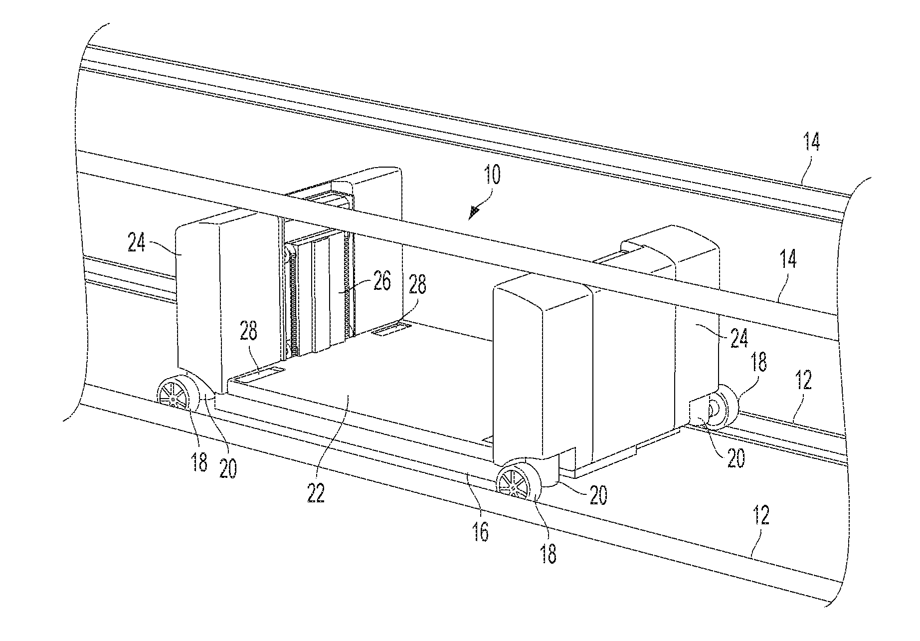
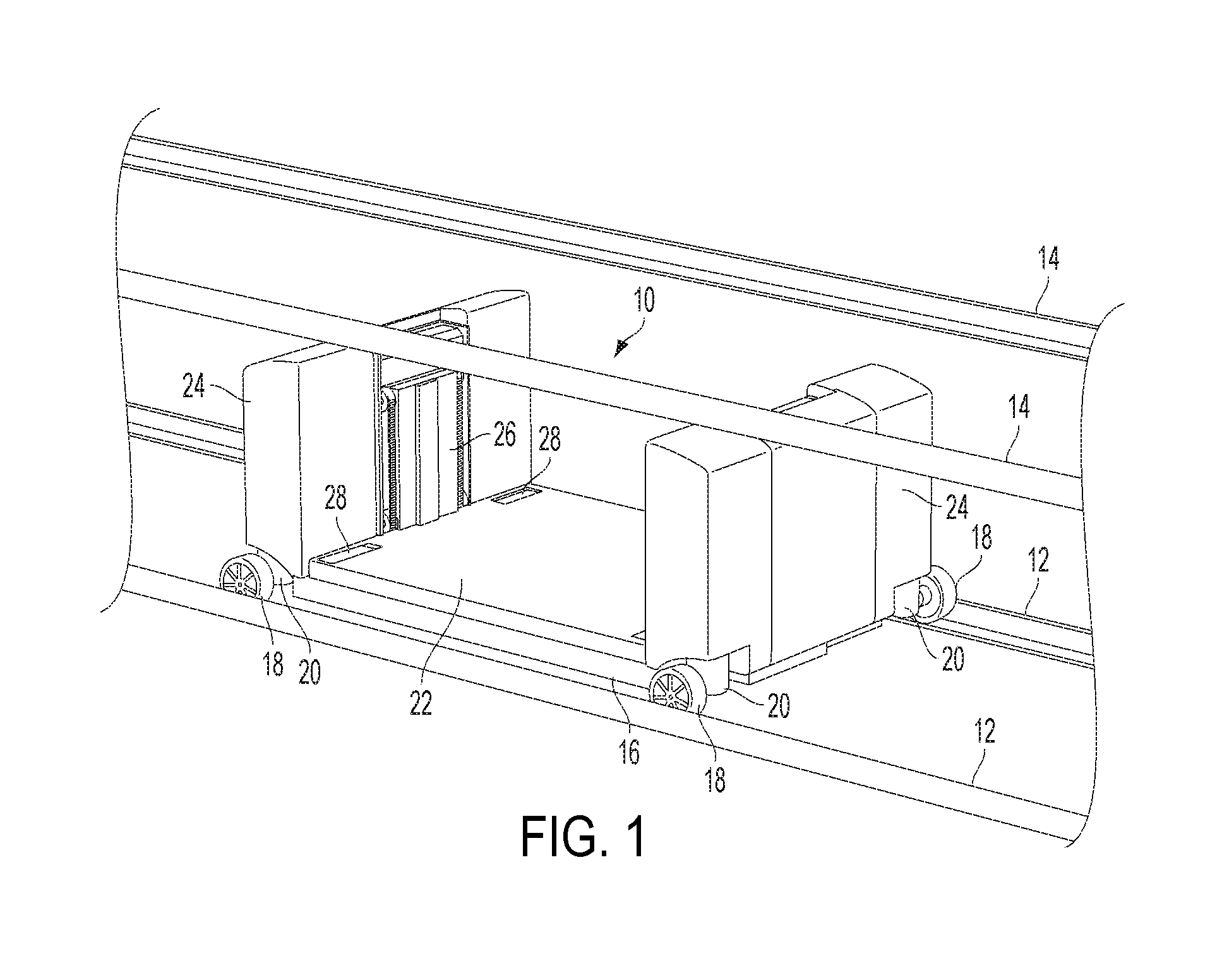
[0037]FIG. 1 shows an exemplary embodiment of a robotic device 10 of the present disclosure. The robotic device 10 may move along a pair of rails 12 that extends in a horizontal direction. FIG. 1 shows only rails extending in a single horizontal direction. However, the robotic system of the present disclosure may also include horizontal rails perpendicular to the rails 12 shown in FIG. 1. As discussed below, the robotic device 10 may move along the rails arranged in mutually perpendicular horizontal directions.

[0038]The rails 12 may be arranged in multiple rows arranged in a vertical direction on different levels with respect to the ground. FIG. 1 shows a pair of rails 12 on which the robotic device 10 currently stands, and ...


PUM


Abstract

A robotic device movable in first, second and third mutually perpendicular directions along rails arranged in multiple rows, where the rails in a row are arranged along the first and second mutually perpendicular directions, and the multiple rows are arranged along the third direction perpendicular to the first and second directions. The robotic device has a frame, wheels coupled to the frame for moving the frame along the rails in the first and second directions, and support handles for lifting the frame in the third direction from first rails arranged in a first row of the rails to second rails arranged in a second row of the rails. The support handles are configured for providing engagement with the second rails so as to lift the robotic device in the third direction from the first rails to the second rails.

Description

TECHNICAL FIELD[0001]This disclosure relates to robotics, and more particularly, to a robotic device that can move in three mutually perpendicular directions without assistance of external lifts.BACKGROUND ART[0002]Conventional robotic systems include lifts provided for moving robotic devices in a vertical direction. However, the number of lifts in any efficient robotic system employing multiple robots is substantially less than the number of robots. Therefore, “bottlenecks” are created near the lifts, reducing the throughput of the robotic system.[0003]Therefore, there is a need for a new “self-lifting” technique that would enable a robotic device to move in three mutually perpendicular directions without assistance of an external lift.SUMMARY OF THE DISCLOSURE[0004]In accordance with one aspect, the present disclosure offers a robotic device movable in first, second and third mutually perpendicular directions along rails arranged in multiple rows, where the rails in a row are arra...

Claims


Application Information

Patent Timeline
Patent Type & Authority Applications(United States)
IPC IPC(8): B65G35/06
CPCB65G1/0492
Inventor RAZUMOV, SERGEY N.
Owner OTTOS CONSULTANTS LTD
Why Eureka
Try Eureka