Snare drum

a snare drum and side head technology, applied in the field of snare drums, can solve the problems of difficult air and sound pressure to be conveyed between the side head and the snare wire, the conventional snare drum can not generate sound, and the use of the snare drum, etc., to achieve the effect of reducing sound volume, durable area without through-holes, and reducing sound volum

Active Publication Date: 2014-01-30
YAMAHA CORP
View PDF3 Cites 9 Cited by
  • Summary
  • Abstract
  • Description
  • Claims
  • Application Information

AI Technical Summary

Benefits of technology

[0006]In a case where the head member having the multiplicity of through-holes and applied to the conventional drum is used as a batter head of a snare drum, however, it is hard to convey air and sound pressure to a snare side head and a snare wire even though the batter head is displaced and vibrated by strikes on the batter head with sticks. Therefore, the conventional snare drum can hardly generate sound peculiar to snare drum which should be brought about by the snare side head and the snare wire. Due to the multiplicity of through-holes provided on the batter head, furthermore, the vibrations of the batter head quickly decay, so that the air traveled to the snare side head and the snare wire will not persist to fail to realize natural sustain which should be realized by a snare drum.

Problems solved by technology

In a case where the head member having the multiplicity of through-holes and applied to the conventional drum is used as a batter head of a snare drum, however, it is hard to convey air and sound pressure to a snare side head and a snare wire even though the batter head is displaced and vibrated by strikes on the batter head with sticks.
Therefore, the conventional snare drum can hardly generate sound peculiar to snare drum which should be brought about by the snare side head and the snare wire.
Therefore, the snare drum having the batter head of the head member having the multiplicity of through-holes is disadvantageous in that the snare drum can be used for practice, but cannot be used for actual music performance.
Furthermore, the snare drum is also disadvantageous in that the multiplicity of through-holes provided on the batter head which will be struck significantly degrade durability of the batter head.

Method used


Image

  • Snare drum
  • Snare drum
  • Snare drum

Examples


first embodiment

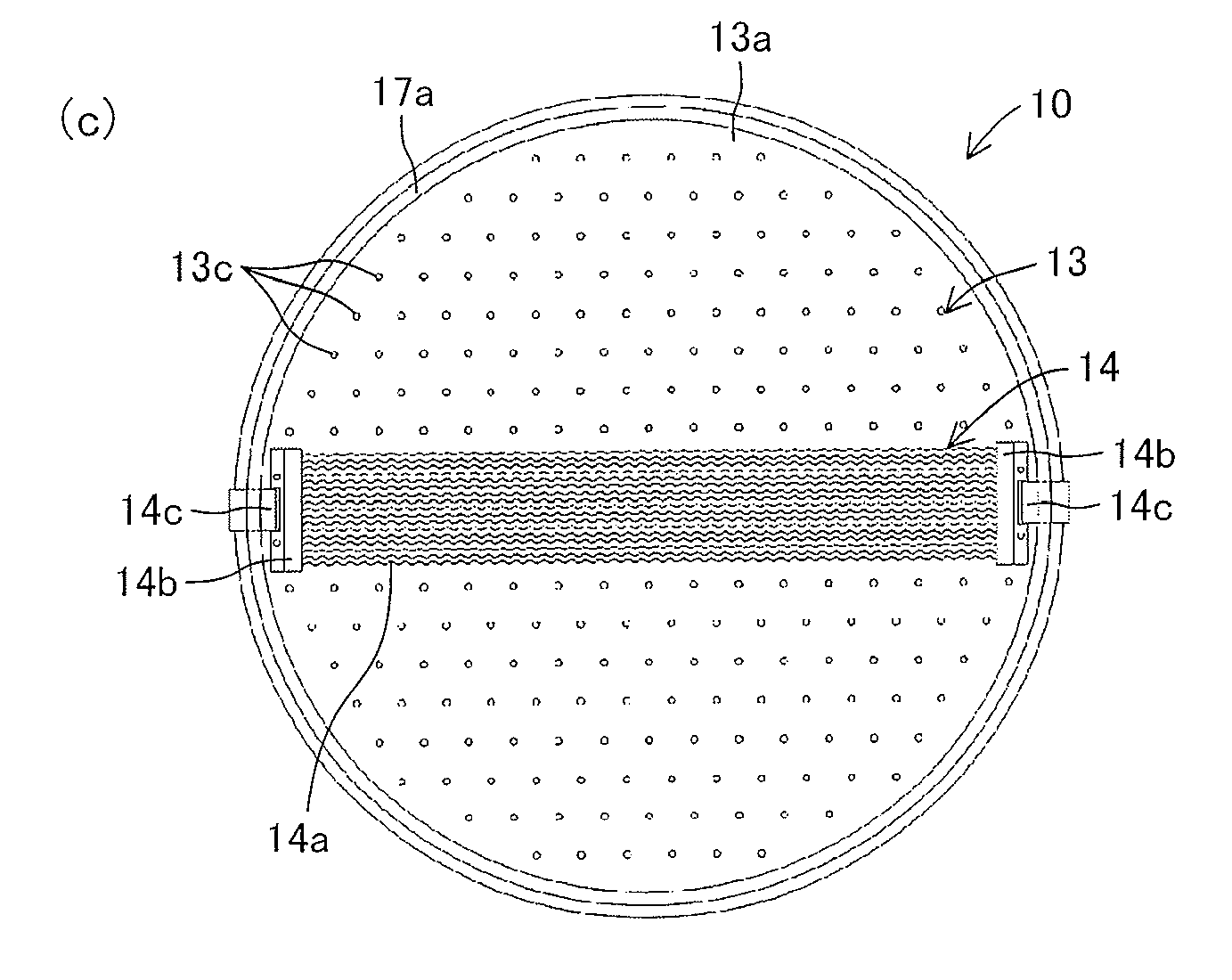
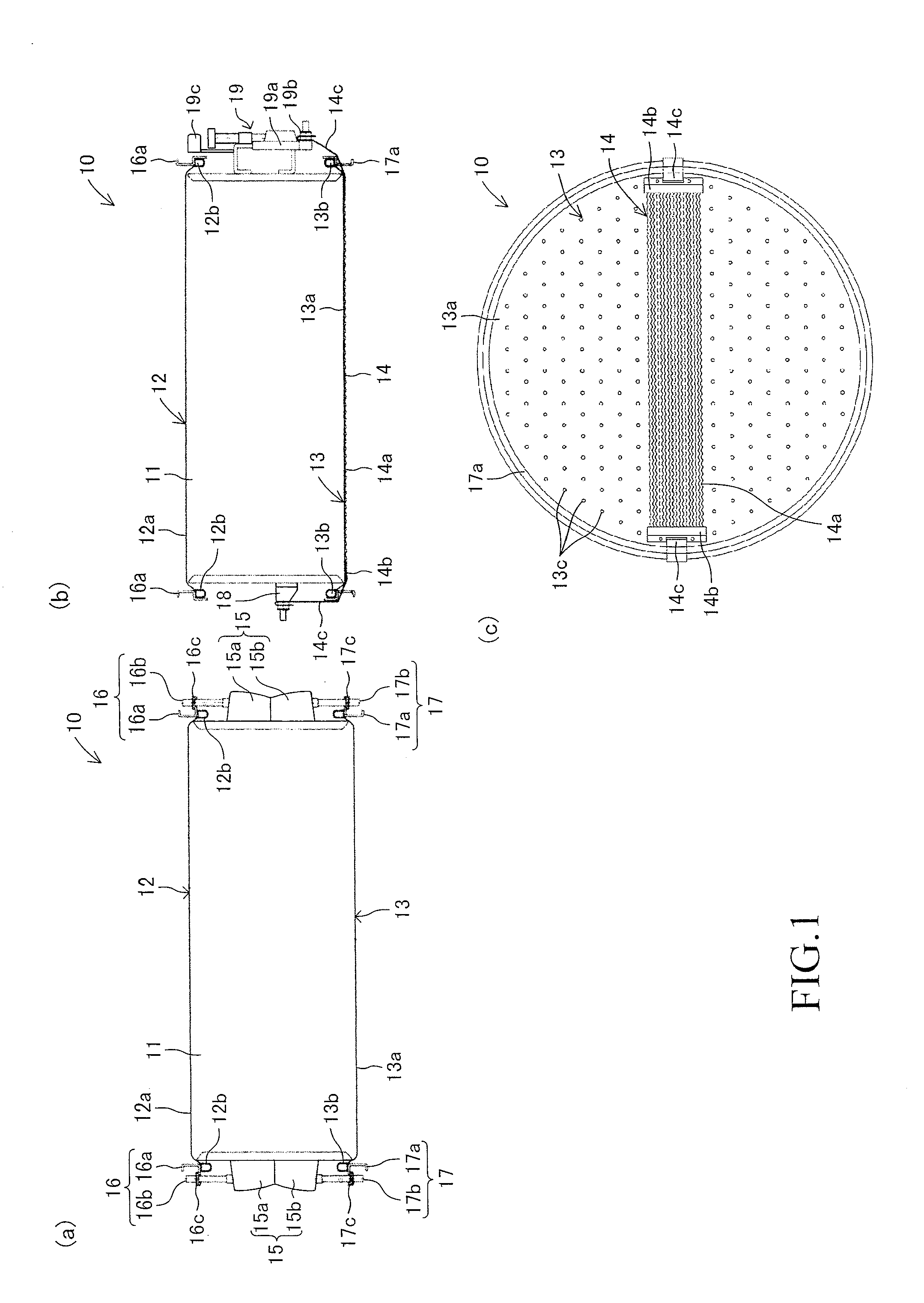
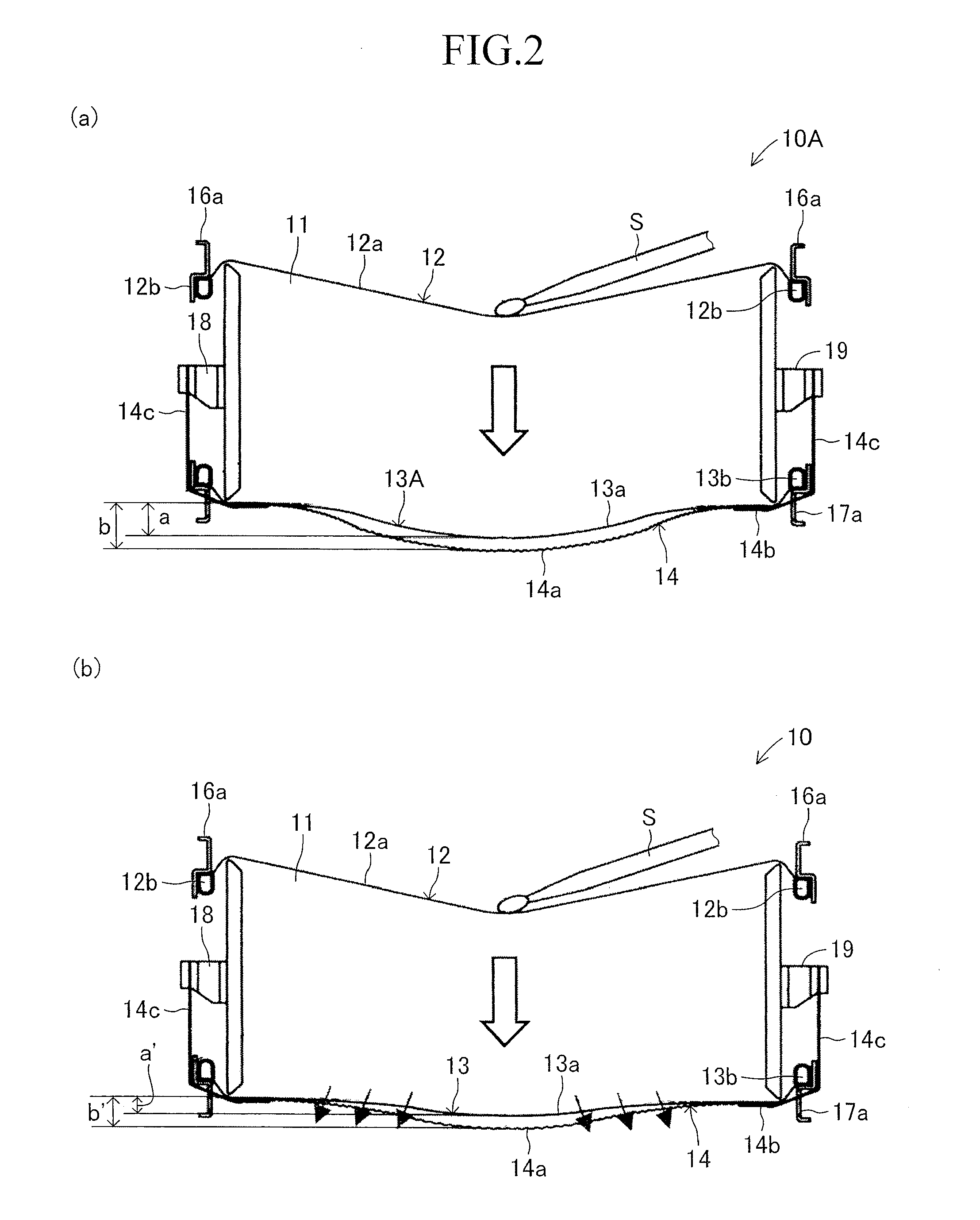
[0028]Hereafter, a snare drum according to the first embodiment of the present invention will be described with reference to the drawings. FIGS. 1 (a) to (c) show a snare drum 10 according to the embodiment. The snare drum 10 is a snare drum measuring 14 inches in diameter, and has a hollow cylindrical shell 11 which is a drum shell, a circular batter head 12 mounted on an upper opening (one end) of the shell 11, a circular snare side head 13 mounted on a lower opening (the other end) of the shell 11, and a snare wire 14 mounted on the bottom surface of the snare side head 13.

[0029]The shell 11 is made of wood (birch) and has functions of efficiently conveying internal air downward when vibrations occur and of reverberating the vibrations inside the shell 11. The batter head 12 is formed of a circular head portion 12a made of a PET (polyethylene terephthalate) film and a flesh hoop 12b which is a metal ring. The head portion 12a has a thickness of 250 μm, and has a slightly larger d...

second embodiment

[0050]FIG. 5 indicates a bottom surface of a snare drum 20 according to the second embodiment of the present invention. The snare drum 20 has circular through-holes 23c all over a snare side head 23. The through-holes 23c have the same diameter and pitch as those of the above-described through-holes 13c. Except the through-holes 23c, the snare drum 20 is configured similarly to the above-described snare drum 10. Therefore, similar components are given similar numerals to omit explanations of the components.

[0051]As for the snare drum 20, because the through-holes 23c are provided all over the snare side head 23, the durability of the snare side head 23 is reduced, but the entire surface of the snare side head 23 can be used to decrease the sound volume. In addition, the snare drum 20 eliminates necessity for the user to care about the direction of the snare side head 23 for attaching the snare side head 23 to the shell 11. Therefore, the snare drum 20 facilitates installation of the...

third embodiment

[0053]FIG. 8 indicates a bottom surface of a snare drum 30 according to the third embodiment of the present invention. The snare drum 30 has circular through-holes 33c which is provided on a snare side head 33 and whose diameter and pitch are larger than the above-described through-holes 13c but have the same through-hole rate as the through-holes 13c. In other words, the through-holes 33c have a larger diameter than the diameter of the through-holes 13c, while the number of the through-holes 33c is reduced in proportion to the enlarged diameter. Except the through-holes 33c, the snare drum 30 is configured similarly to the above-described snare drum 10. Therefore, similar components are given similar numerals to omit explanations of the components.

[0054]The snare drum 30 have the through-holes 33c having a larger diameter, which facilitates outflow of air. As a result, the amplitude of the snare drum 30 is lower than the amplitude of the above-described snare drum 10. In other word...


PUM


Abstract

A snare drum 10 has a hollow cylindrical shell 11, a batter head 12 mounted on one end of the shell 11, a snare side head 13 mounted on the other end of the shell 11 and a snare wire 14 whose both ends are held by the both sides of the shell 11 to span across the surface of the snare side head 13. The snare side head 13 has a plurality of through-holes 13c. As a result, the snare drum 10 reduces sound volume while maintaining natural timbre and feeling of striking a snare drum.

Description

BACKGROUND OF THE INVENTION[0001]1. Field of the Invention[0002]The present invention relates to a snare drum with reducing sound volume.[0003]2. Description of the Related Art[0004]Acoustic drums are musical instruments which generate loud sound. Depending on the venue where the acoustic drums are played, therefore, the sound volume of the acoustic drums are too loud. In some cases, furthermore, acoustic drums are adjusted to reduce the sound volume of the acoustic drums due to significant differences in sound volume between the other musical instruments. Conventionally, therefore, a head member of a surface where a player strikes are replaced with a mesh head, or a rubber pad is provided on a head member to reduce sound volume. An example of such conventional drums is a drum whose head member has a multiplicity of through-holes to reduce sound volume (for example, see Japanese Patent Publication No. 3835084).[0005]This drum has a hollow cylindrical shell and a sheet-type head memb...

Claims


Application Information

Patent Timeline
Patent Type & Authority Applications(United States)
IPC IPC(8): G10D13/02
CPCG10D13/025G10D13/02G10D13/20G10D13/18G10D13/10
Inventor HASHIMOTO, RYUJI
Owner YAMAHA CORP
Why Eureka
Try Eureka