Frequency multiplier circuit and system

a frequency multiplier and circuit technology, applied in the field of frequency multipliers, can solve the problems of large chip cost, structure defects, and difficulty in design, and achieve the effects of precise frequency multiplication, simple structure, and cheap and easy cascad

Inactive Publication Date: 2014-01-30
IPGOAL MICROELECTRONICS (SICHUAN) CO LTD
View PDF3 Cites 0 Cited by
  • Summary
  • Abstract
  • Description
  • Claims
  • Application Information

AI Technical Summary

Benefits of technology

[0006]An object of the present invention is to provide a frequency multiplier circuit which is simple, cheap and easy to cascade and provides precise frequency multiplication.
[0009]Compared with prior arts, the frequency multiplier circuit and the system thereof, provided by the present invention, are able to double frequency precisely and have advantages of a big bandwidth, a simple structure and being easy to cascade.

Problems solved by technology

The conventional frequency multiplier usually has a structure of phase locked loop (PLL) to satisfy requirements of the high precision and the low noise, but the structure has defects of a big cost of chips and difficulty in designing.

Method used


Image

  • Frequency multiplier circuit and system
  • Frequency multiplier circuit and system

Examples


Embodiment Construction

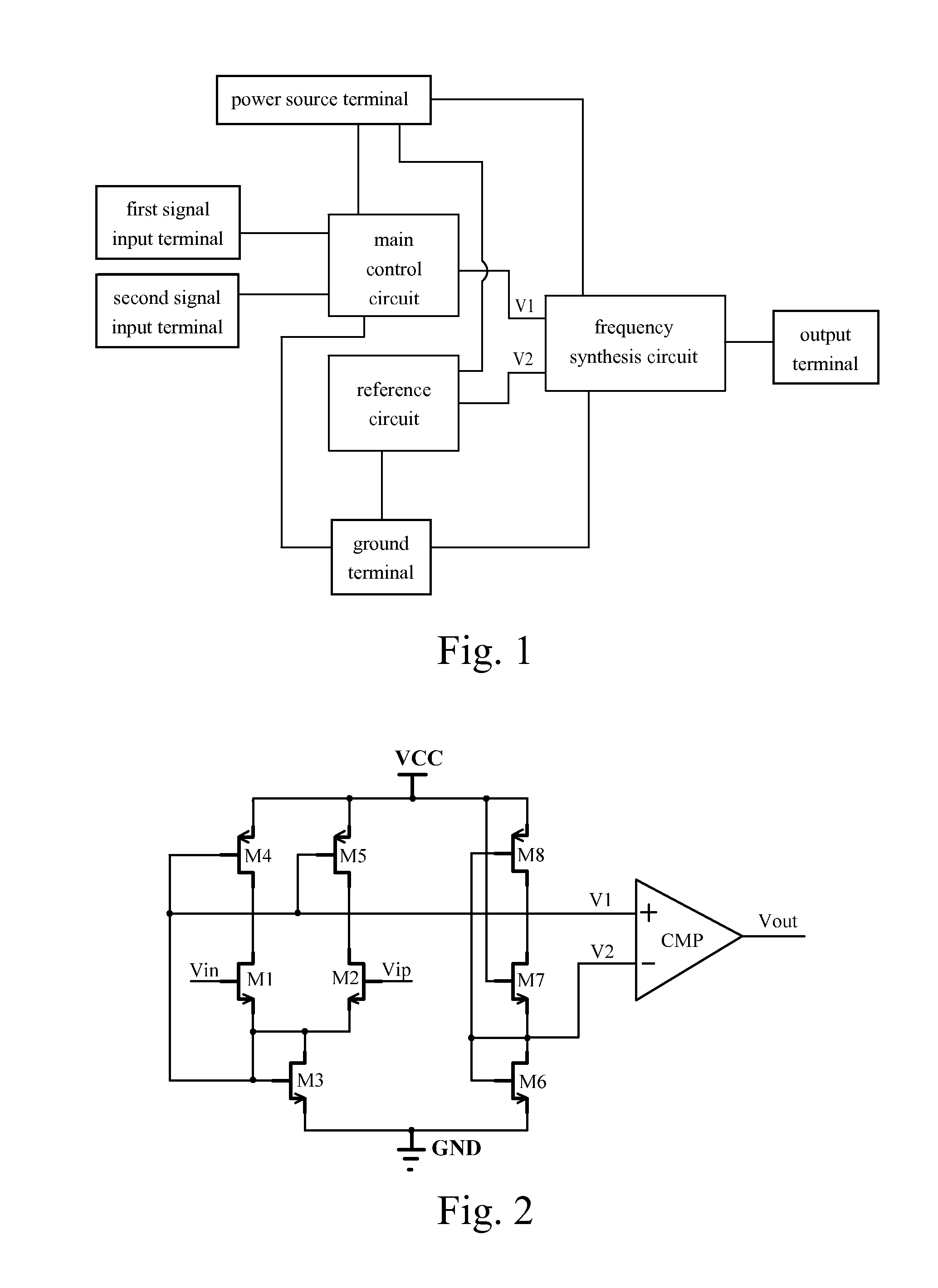
[0013]Referring to FIG. 1 of the drawings, according to a preferred embodiment of the present invention, a frequency multiplier circuit comprises a first signal input terminal Vin, a second signal input terminal Vip, an output terminal Vout, a power source terminal VCC, a ground terminal GND, a main control circuit which is connected to the first signal input terminal Vin, the second signal input terminal Vip, the power source terminal VCC and the ground terminal GND, and a frequency synthesis circuit which is connected to the main control circuit, the reference circuit, the output terminal Vout, the power source terminal VCC and the ground terminal GND.

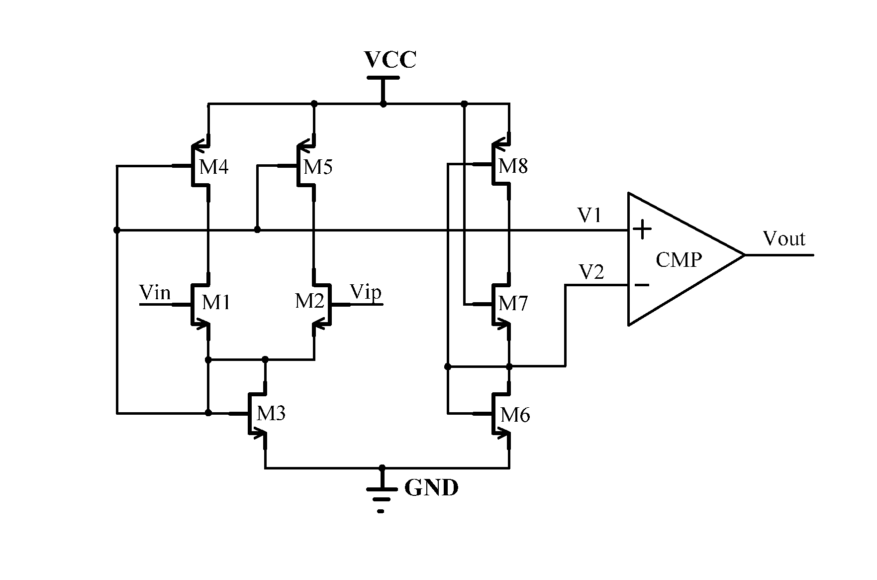
[0014]Further referring to FIG. 2, according to the preferred embodiment of the present invention, a frequency multiplier circuit is showed, wherein the main control circuit comprises a first FET M1, a second FET M2, a third FET M3, a fourth FET M4, a fifth FET M5; the reference circuit comprises a sixth FET M6, a seventh FET M7, an ...


PUM


Abstract

A frequency multiplier circuit includes a first signal input terminal, a second signal input terminal, an output terminal, a power source terminal, a ground terminal, a main control circuit which is connected to the first signal input terminal, the second signal input terminal, the power source terminal and the ground terminal, a reference circuit which is connected to the power source terminal and the ground terminal, and a frequency synthesis circuit which is connected to the main control circuit, the reference circuit, the output terminal, the power source terminal and the ground terminal.

Description

BACKGROUND OF THE PRESENT INVENTION[0001]1. Field of Invention[0002]The present invention relates to a frequency multiplier, and more particularly to a frequency multiplier circuit which is simple in structure and easy to cascade and provides precise frequency multiplication and a system thereof.[0003]2. Description of Related Arts[0004]The frequency multiplier is a circuit which generates an output signal whose frequency is a multiple of the frequency of an input frequency, for accomplishing multiplying frequency signals. Generally, a working clock of a digital circuit requires the frequency multiplier to have a high precision and a low noise. The ratio of the input clock to the input clock is called the frequency multiplication times.[0005]The conventional frequency multiplier usually has a structure of phase locked loop (PLL) to satisfy requirements of the high precision and the low noise, but the structure has defects of a big cost of chips and difficulty in designing. Thus it i...

Claims


Application Information

Patent Timeline
Patent Type & Authority Applications(United States)
IPC IPC(8): H03B19/14
CPCH03B19/14
Inventor FAN, FANGPING
Owner IPGOAL MICROELECTRONICS (SICHUAN) CO LTD
Why Eureka
Try Eureka