Parking device for a bicycle

a technology for bicycles and parking devices, applied in the direction of bicycle stands, cycle equipment, vehicle maintenance, etc., can solve the problem of not recommended installation of kickstands on bicycles

Inactive Publication Date: 2014-02-06
ASHIMA LTD
View PDF5 Cites 6 Cited by
  • Summary
  • Abstract
  • Description
  • Claims
  • Application Information

AI Technical Summary

Problems solved by technology

Recently, riding bicycle is quite common for people as a leisure activity, and how to park the bicycle becomes an important issue.
In contrast, for those cross-country bicycles, especially for those which rides in the forests or downhill, in order to absorb impacts from the unsmooth roads, these bicycles have a buffer structure so that t

Method used


Image

  • Parking device for a bicycle
  • Parking device for a bicycle
  • Parking device for a bicycle

Examples


second embodiment

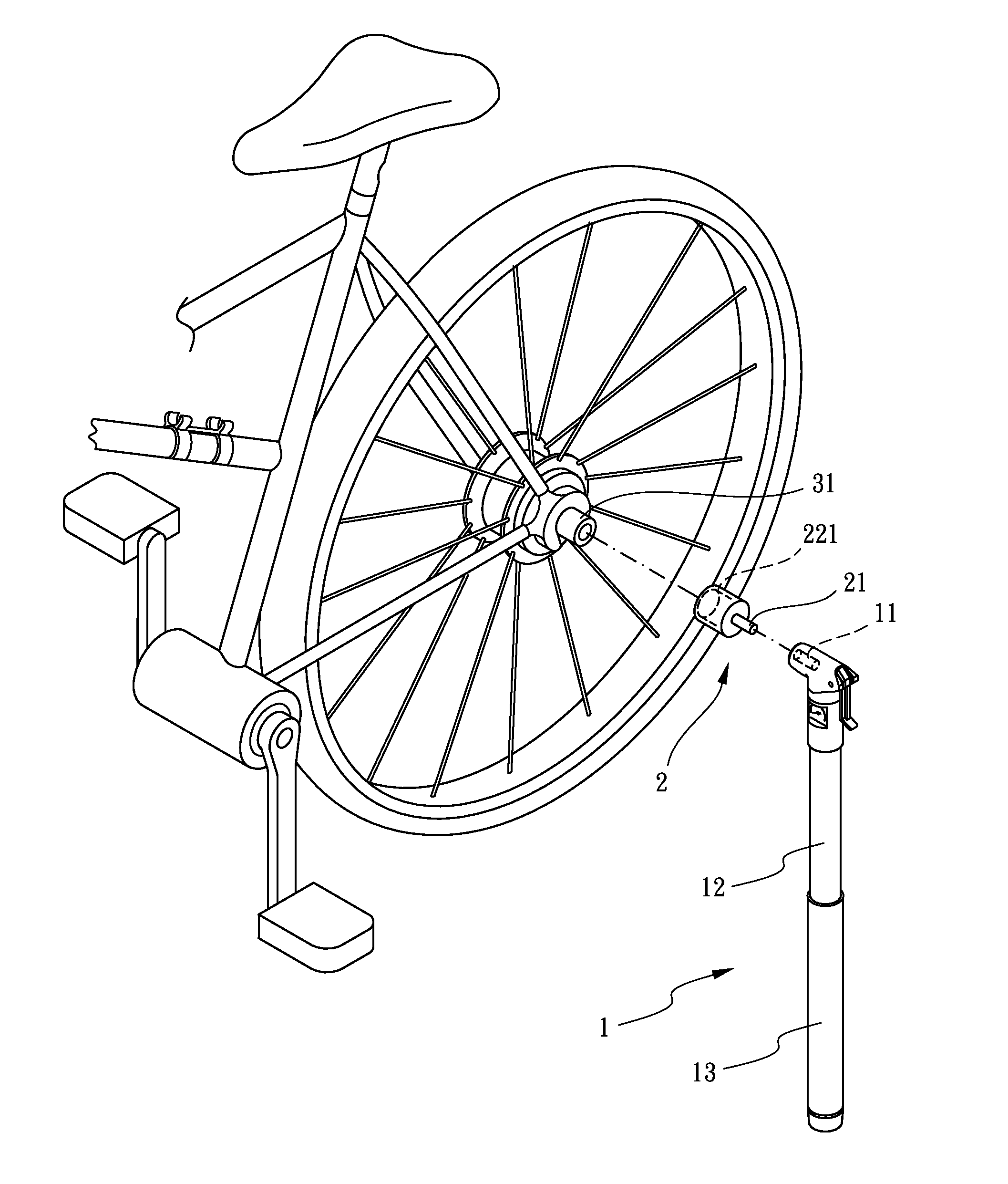
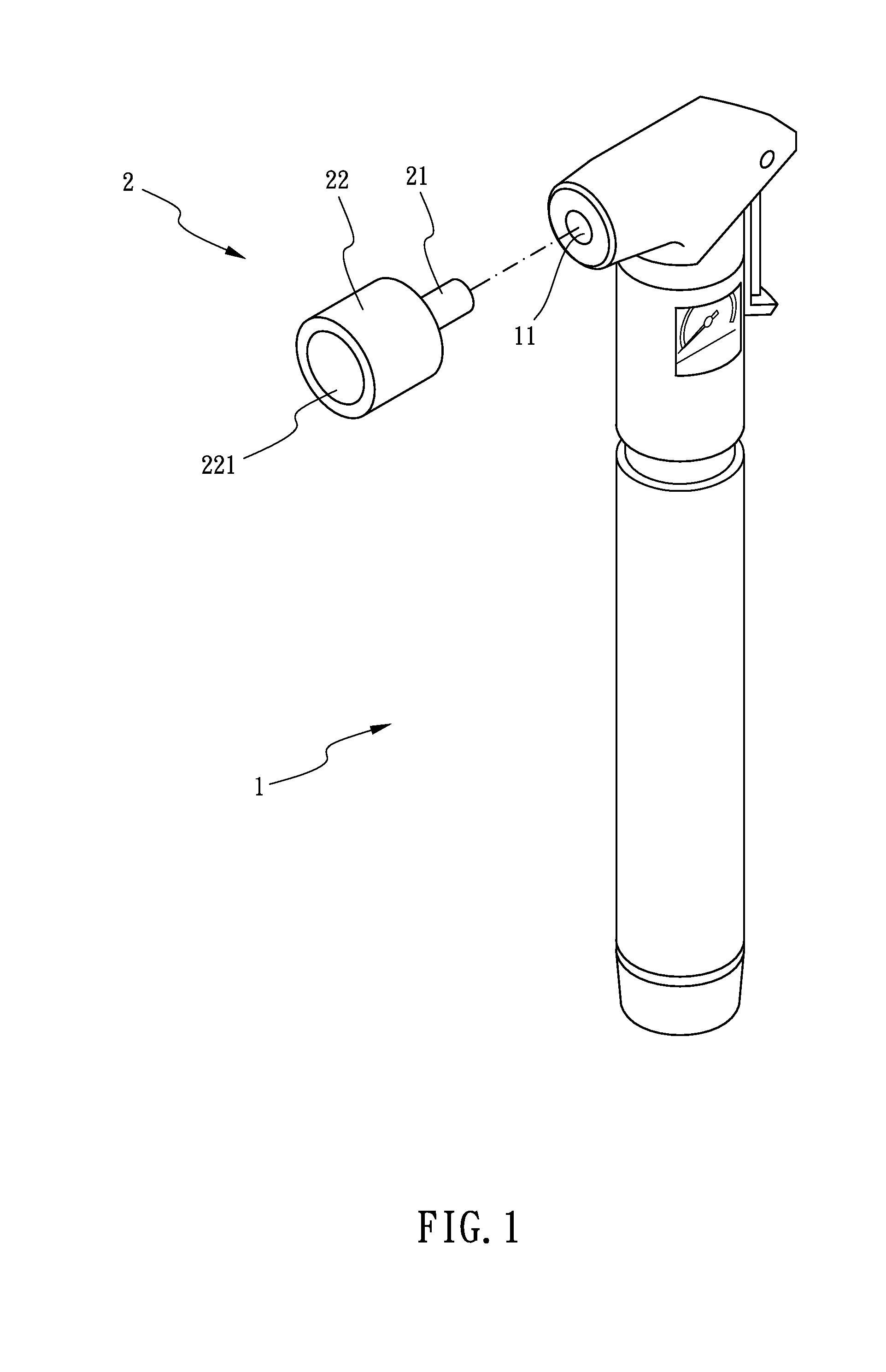
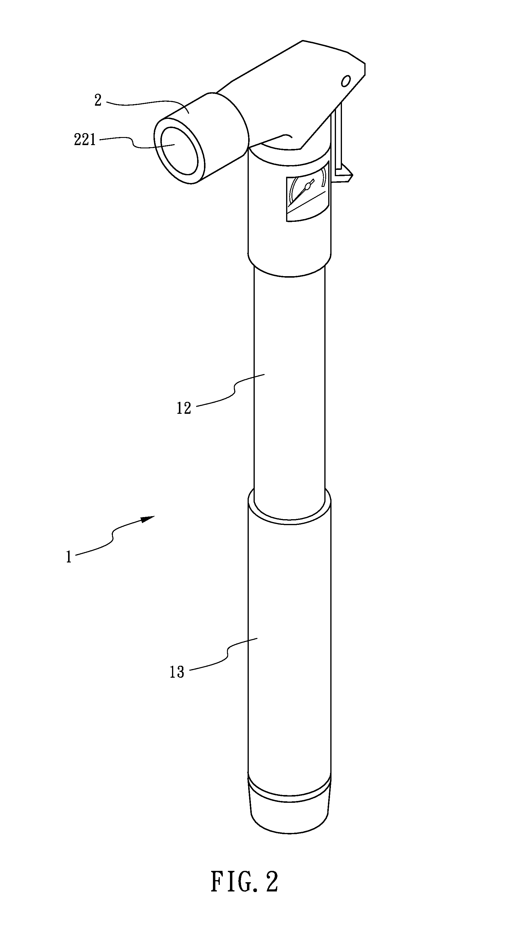
[0032]Under this arrangement, the inflator 1 is assembled into the crank hole 321 of the crank axle 32 of the bicycle via the connecting member 2, and the outer cylinder 13 is axially moved relative to the inner cylinder 12 so that the total length of the inflator 1 is shortened for parking, and the terminal of the inflator 1 is stand on the grounds. In the second embodiment, the inflator 1 is assembled on the crank axle 32 which is closer to the middle part of the bicycle longitudinally, namely, a position between a front wheel and a rear wheel of the bicycle, therefore, the inflator 1, the front wheel and the rear wheel contact with the ground and form a triangle to provide the user a better way to park the bicycle more stably.

third embodiment

[0033]Referring to FIG. 8 and FIG. 9, the present invention comprises an inflator 4, a locking assembly 5 and a connecting member 6.

[0034]The inflator 4 has an inner cylinder 41 and an outer cylinder 42. The outer cylinder 42 is axially assembled to one end of the inner cylinder 41. The outer cylinder 42 is axially moved relative to the inner cylinder 41 to elongate or to shorten the length of the inflator 4. A nozzle 43 is assembled to another end of the inner cylinder 41.

[0035]The locking assembly 5 is assembled on one end of the outer cylinder 42 which is assembled to the inner cylinder 41. The locking assembly 5 locks or unlocks the movement of the outer cylinder 42 relative to the inner cylinder 41.

[0036]The connecting member 6 has an inserting part 61 at one end thereof and an assembling part 62 at another end thereof. The inserting part 61 of the connecting member 6 is inserted into the nozzle 43. The assembling part 62 is assembled on the terminal part of a wheel axle 31. Th...

fourth embodiment

[0038]Referring to FIG. 10 and FIG. 11, the present invention comprises an inflator 7 and a connecting member 8.

[0039]The inflator 7 has a nozzle 71 defined thereon. The inflator 7 has an inner cylinder 72 and an outer cylinder 73. The outer cylinder 73 is axially moved relative to the inner cylinder 72 to elongate or to shorten the length of the inflator 7. The outer cylinder 73 is axially assembled to one end of the inner cylinder 72. The nozzle 71 is assembled to another end of the inner cylinder 72.

[0040]The connecting member 8 has an inserting part 81 at one end thereof and an assembling part 82 at another end thereof. The inserting part 81 of the connecting member 8 is inserted into the nozzle 71. The assembling part 82 has an engaging groove 821 opened thereon, and the engaging groove821 of the assembling part 82 is buckledly connected to a crank arm 33 of the bicycle (in this embodiment, the engaging groove buckledly connected to a chain stay of the bicycle.).

[0041]Under thi...


PUM


Abstract

A parking device for a bicycle includes an inflator and a connecting member. The inflator has a nozzle defined thereon. The connecting member has an inserting part at one end thereof and an assembling part at another end thereof. The inserting part of the connecting member inserted into the nozzle, the assembling part assembled on the bicycle. Under this arrangement, a user connects the inflator to the bicycle via the connecting member to park the bicycle stably; in contrast, when the user wants to ride the bicycle, the connecting member and the inflator are able to be assembled on the bicycle.

Description

BACKGROUND OF THE INVENTION[0001]1. Field of the Invention[0002]The present invention relates to a parking device, and more particularly to a parking device for a bicycle.[0003]2. Description of Related Art[0004]Recently, riding bicycle is quite common for people as a leisure activity, and how to park the bicycle becomes an important issue. Generally, a rider can use a conventional kickstand to park a bicycle. However, for the bicycles which are applied in speed racing, installing the conventional kickstand as an additional component is forbidden so as to avoid the personnel from damaging when bicycles collide with each other or collapse. In contrast, for those cross-country bicycles, especially for those which rides in the forests or downhill, in order to absorb impacts from the unsmooth roads, these bicycles have a buffer structure so that to install an additional conventional kickstand on the bicycles is not easy; moreover, when the rider rides the bicycle in the tree-lined roads...

Claims


Application Information

Patent Timeline
IPC IPC(8): B60S9/12
CPCB62H1/00B62H3/00
Inventor MOORE, WAYNE-IAN
Owner ASHIMA LTD
Why Eureka
Try Eureka