Liquid Ejection Apparatus And Control Method For Liquid Ejection Apparatus

Active Publication Date: 2014-02-27
SEIKO EPSON CORP
View PDF4 Cites 18 Cited by
  • Summary
  • Abstract
  • Description
  • Claims
  • Application Information

AI Technical Summary

Benefits of technology

[0009]An advantage of some aspects of the invention is to provide a liquid election apparatus and a control method therefor which en

Problems solved by technology

Particularly, in these days, there sometimes occurs a case where the liquid ejection apparatus is used in an application which causes liquid to be ejected at a higher drive frequency while causing a liquid ejection head and a landing object to perform a relative movement at a higher speed, and in this case, the variation of the landing position of liquid results in being significant.
Moreover, there is a problem that, in a printer in which an ink jet type recording head, which is a kind of liquid ejection head, is mounted, in the case where a configuration in which inks of the same color are ejected through respective nozzles which are included in mutually different nozzle lines is employed, any variation of a landing position of ink between the inks of the same color results in the degradation

Method used


Image

  • Liquid Ejection Apparatus And Control Method For Liquid Ejection Apparatus
  • Liquid Ejection Apparatus And Control Method For Liquid Ejection Apparatus
  • Liquid Ejection Apparatus And Control Method For Liquid Ejection Apparatus

Examples


Embodiment Construction

[0023]Hereinafter, an embodiment to practice the invention will be described with reference to the accompanying drawings. It is to be noted here that, although various restrictions are imposed on an embodiment described below which is positioned as a preferable specific example of the invention, the scope of the invention is not restricted to such an embodiment, provided that, in description below, there is not any particular notice for notifying a restriction on the invention. Further, hereinafter, description will be made by exemplifying an ink jet type recording apparatus (hereinafter, referred to as just a printer) as a liquid ejection apparatus according to an aspect of the invention.

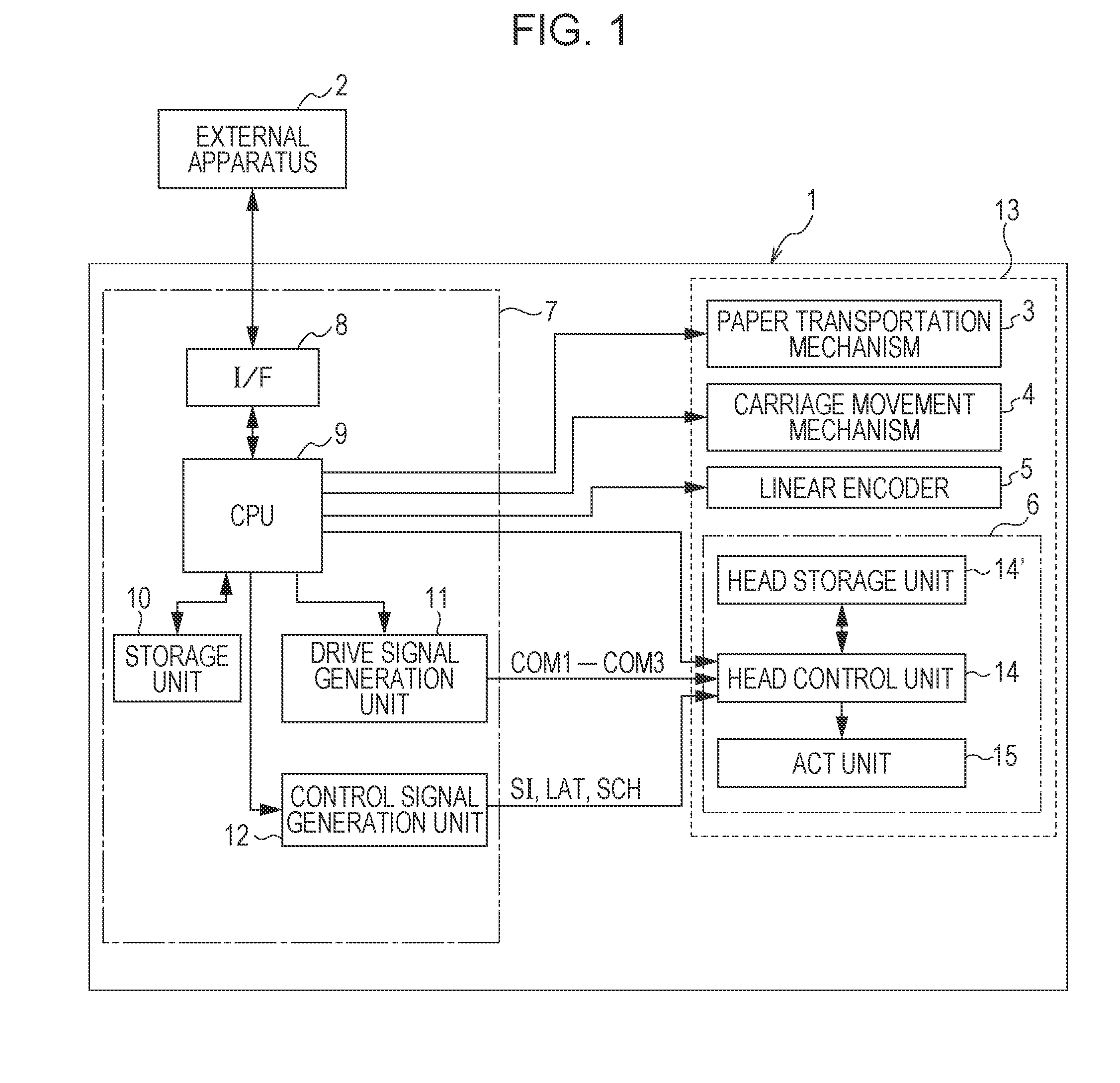
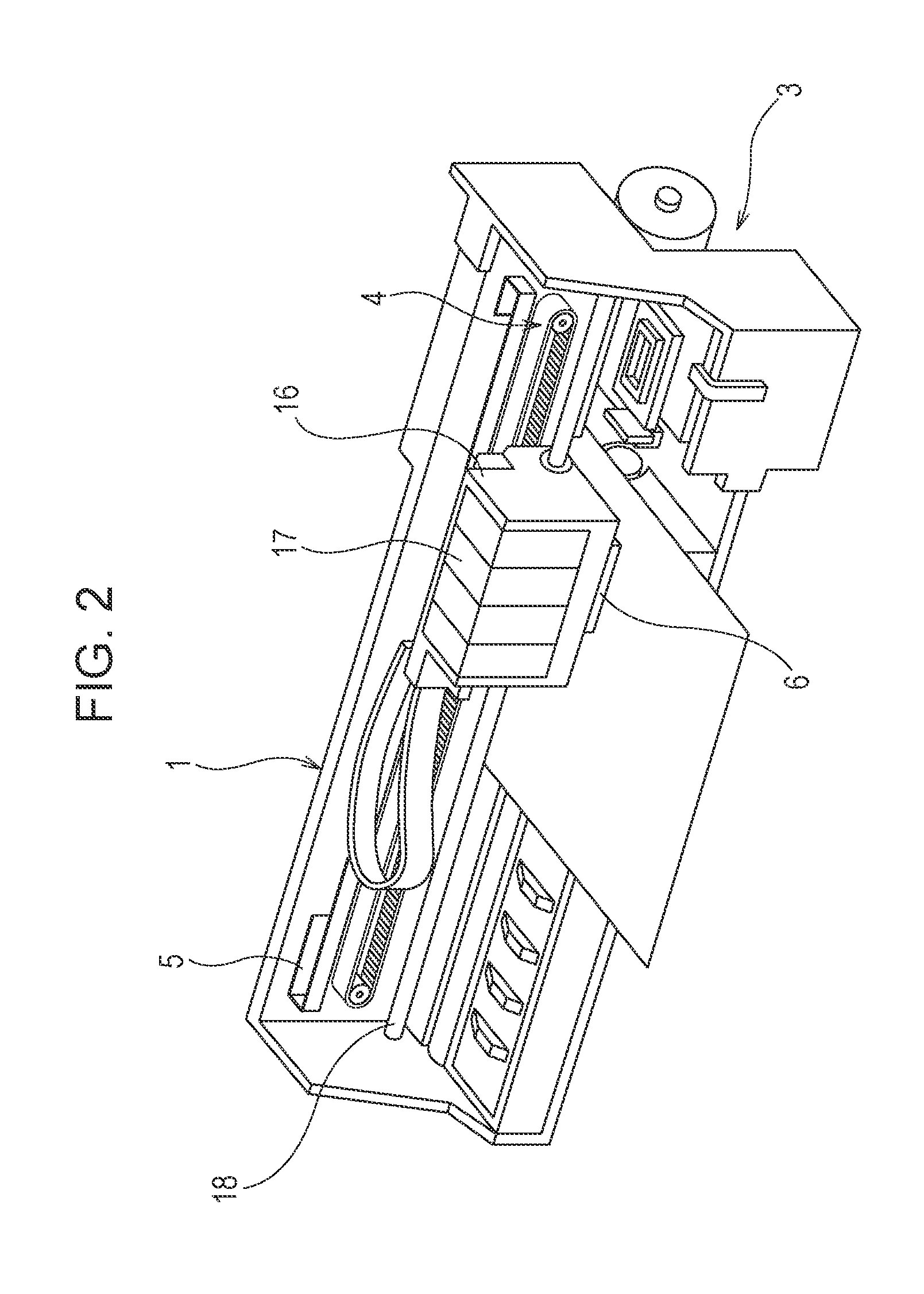
[0024]FIG. 1 is a block diagram illustrating an electric configuration of a printer 1, and FIG. 2 is a perspective view of an internal configuration of the printer 1. An external apparatus 2 is an electronics device, such as a computer or a digital camera, which deals with images. This external app...


PUM


Abstract

A printer controller outputs plural drive signals including respective series of drive pulses, the timing points of which are different from one another, to a head control unit side, and outputs a multiplexed signal resulting from multiplexing change signals corresponding to the respective drive signals to a head control unit side, and the head control unit includes a control signal demultiplexing unit which demultiplexes the multiplexed signal into the change signals corresponding to respective nozzle rows, and an actuator control unit which, on the basis of each of the demultiplexed change signals, selects one of the drive pulses included in one of the drive signal which corresponds to the demultiplexed change signal, and applies the selected drive pulse to a piezoelectric element included in one of the nozzle rows which corresponds to the drive signal corresponding to the demultiplexed change signal.

Description

BACKGROUND[0001]1. Technical Field[0002]The present invention relates to liquid ejection apparatuses, such as an ink jet type recording apparatus, and control methods for a liquid ejection apparatus, and in particular, it relates to a liquid ejection apparatus and a control method for a liquid ejection apparatus which cause liquid to be ejected through a nozzle by, in order to drive a pressure generation means to cause a pressure variation of the liquid which is contained inside a pressure chamber communicated with the nozzle, applying a drive waveform included in a drive signal to the pressure generation means.[0003]2. Related Art[0004]A liquid ejection apparatus is an apparatus which is provided with an ejection head, and ejects (discharges) various kinds of liquid from the ejection head. Well-known examples of this liquid ejection apparatus include an image recording apparatus, such as an ink jet type printer and an ink jet type plotter, and further, nowadays, this liquid ejectio...

Claims


Application Information

Patent Timeline
IPC IPC(8): B41J2/07
CPCB41J2/07B41J2/04546B41J2/04581B41J2/04588B41J2/04595B41J2/04596B41J2/04521
Inventor USUI, TOSHIKI
Owner SEIKO EPSON CORP
Why Eureka
Try Eureka