Single direct current arc chute, and bi-directional direct current electrical switching apparatus employing the same

Active Publication Date: 2014-03-06
EATON INTELLIGENT POWER LIMITED
View PDF2 Cites 36 Cited by
  • Summary
  • Abstract
  • Description
  • Claims
  • Application Information

AI Technical Summary

Benefits of technology

The disclosed concept is a direct current arc chute that is used in a bi-directional, direct current electrical switching apparatus. The arc chute includes a ferromagnetic base, two ferromagnetic side members, and a third ferromagnetic member. The first and second ferromagnetic side members are disposed at the ends of the ferromagnetic base. The third ferromagnetic member is disposed between the first and second ferromagnetic side members. The arc chute also includes a first permanent magnet and a second permanent magnet, as well as a first and second arc chamber. The arc chute is designed to facilitate the opening and closing of the separable contacts and to provide a safe and reliable electrical switching mechanism.

Problems solved by technology

Typically, molded case circuit breakers (MCCBs) are not specifically designed for use in direct current (DC) applications.
One of the challenges in DC interruption is to drive the arc into the arc chute, specifically at relatively low current levels.

Method used


Image

  • Single direct current arc chute, and bi-directional direct current electrical switching apparatus employing the same
  • Single direct current arc chute, and bi-directional direct current electrical switching apparatus employing the same
  • Single direct current arc chute, and bi-directional direct current electrical switching apparatus employing the same

Examples


example 1

[0035]The following factors can increase the magnitude of the magnetic field near the fixed contact 242 (shown in FIG. 8): (1) increasing the thickness of the permanent magnets 216,218; (2) increasing the strength of the material of the permanent magnets 216,218, although relatively stronger magnetic materials are generally susceptible to demagnetization at relatively lower temperatures; (3) decreasing the distance between the separable contacts 238 (shown in FIG. 8) and the intermediate ferromagnetic (e.g., without limitation, steel) member 212; and (4) increasing the distance between the separable contacts 238 and the magnetic field null point 244 (shown in FIG. 7).

example 2

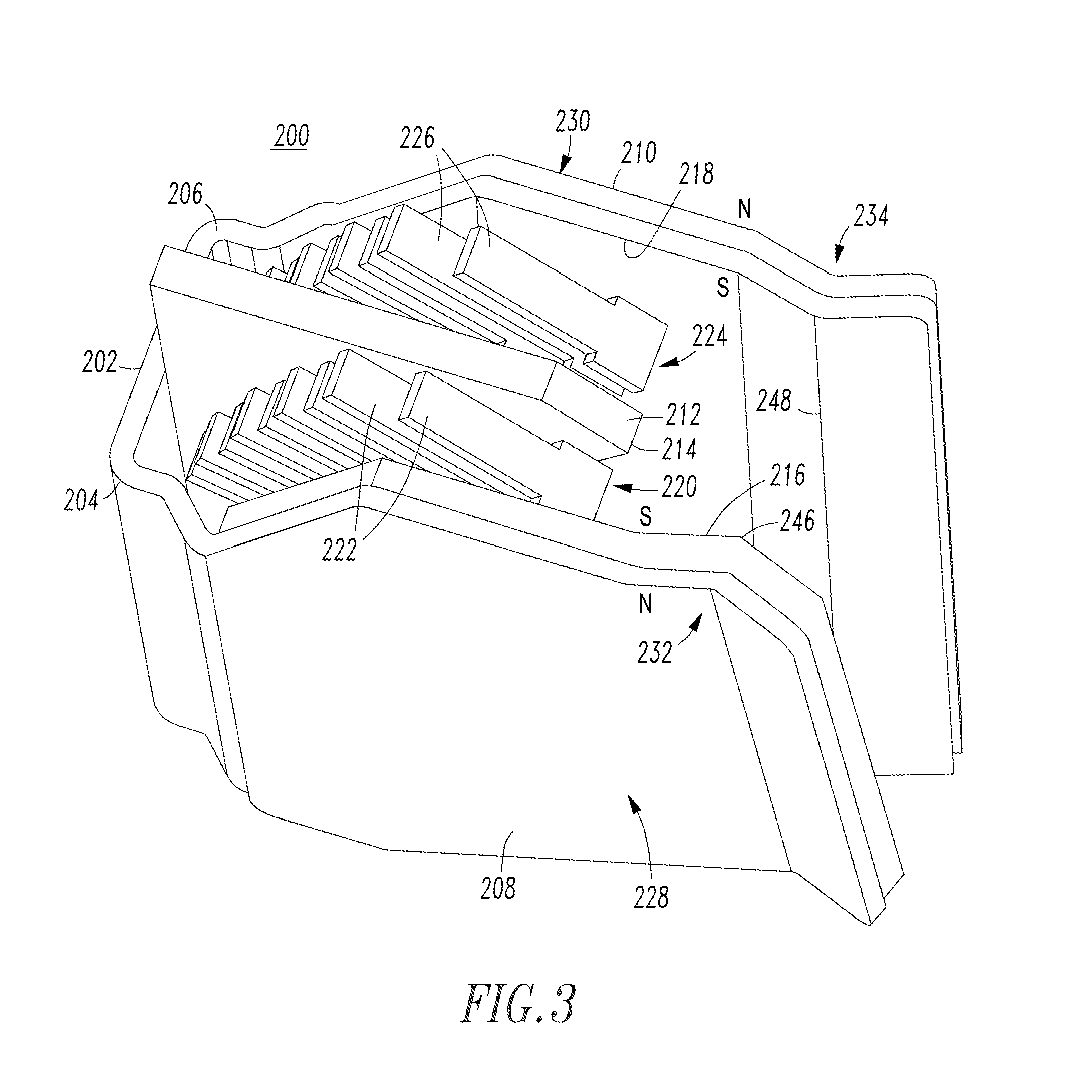
[0036]The first permanent magnet 216 and the first ferromagnetic side member 208 are parallel with the second permanent magnet 218 and the second ferromagnetic side member 210 between the first end 204 of the ferromagnetic base 202 and the end portion 214 of the third ferromagnetic member 212. The second permanent magnet 218 and the second ferromagnetic side member 210 are parallel with the first permanent magnet 216 and the first ferromagnetic side member 208 between the opposite second end 206 of the ferromagnetic base 202 and the end portion 214 of the third ferromagnetic member 212.

example 3

[0037]The first permanent magnet 216 and the first ferromagnetic side member 208 both angle toward the second permanent magnet 218 and the second ferromagnetic side member 210 after the end portion 214 of the third ferromagnetic member 212. The second permanent magnet 218 and the second ferromagnetic side member 210 both angle toward the first permanent magnet 216 and the first ferromagnetic side member 208 after the end portion 214 of the third ferromagnetic member 212. This allows the magnetic field to pull the arc toward the desired arc splitter plates 222 or 226 regardless of the initial arc motion direction. The direction of the magnetic field beyond the end portion 214 of the third ferromagnetic member 212 (between the member 212 and the separable contacts 238 (FIG. 8)) pulls the arc to the first arc chute 220 or to the second arc chute 224, depending on the polarity of the electric current.


PUM


Abstract

A direct current arc chute includes a ferromagnetic base having first and second ends; first and second ferromagnetic side members disposed from the respective first and second ends; a third ferromagnetic member disposed from the base intermediate the side members and having an end portion opposite the base; and first and second magnets on the respective first and second members have a magnetic polarity facing the third member. A first arc chamber is between the first and third members; and a second arc chamber is between the second and third members. The first magnet and first member extend away from the first end and beyond the end portion, and toward the second magnet and second member after the end portion. The second magnet and second member extend away from the second end and beyond the end portion, and toward the first magnet and first member after the end portion.

Description

BACKGROUND[0001]1. Field[0002]The disclosed concept pertains generally to electrical switching apparatus and, more particularly, to direct current electrical switching apparatus, such as, for example and without limitation, direct current circuit breakers. The disclosed concept further pertains to direct current arc chutes.[0003]2. Background Information[0004]Electrical switching apparatus employing separable contacts exposed to air can be structured to open a power circuit carrying appreciable current. These electrical switching apparatus, such as, for instance, circuit breakers, typically experience arcing as the contacts separate and commonly incorporate arc chutes to help extinguish the arc. Such arc chutes typically comprise a plurality of electrically conductive plates held in spaced relation around the separable contacts by an electrically insulative housing. The arc transfers to the arc plates where it is stretched and cooled until extinguished.[0005]Typically, molded case c...

Claims


Application Information

Patent Timeline
IPC IPC(8): H01H33/18
CPCH01H9/36H01H9/443
Inventor JUDS, MARK A.ZHOU, XINKANK, AMOGH V.ROLLMANN, PAUL J.MUELLER, ROBERT W.BARTONEK, MICHAEL F.
Owner EATON INTELLIGENT POWER LIMITED
Why Eureka
Try Eureka