Apparatus and method for isolating flow in a downhole tool assembly

a tool assembly and flow isolating technology, applied in the field of treating wells, can solve the problems of difficult to maintain fluid pressure high enough to cut the casing, not economic success, and inability to perforate with abrasive jets,

Active Publication Date: 2014-03-13
TD TOOLS
View PDF7 Cites 8 Cited by
  • Summary
  • Abstract
  • Description
  • Claims
  • Application Information

AI Technical Summary

Problems solved by technology

It was soon discovered, however, that abrasive jet perforating could not only perforate, but cut (completely sever) the tubular goods into two pieces.
While abrasive jet perforating was a technical success (over 5,000 wells were treated), it was not an economic success.
The tool life in abrasive jet perforating was measured in only minutes and fluid pressures high enough to cut casing were difficult to maintain with pumps available at the time.
Consequently, very little work was performed with abrasive jet perforating technology until the late 1990's.
However, the basic design of abrasive jet perforating tools used today has not changed significantly from those used in the 1960's.

Method used


Image

  • Apparatus and method for isolating flow in a downhole tool assembly
  • Apparatus and method for isolating flow in a downhole tool assembly
  • Apparatus and method for isolating flow in a downhole tool assembly

Examples


Embodiment Construction

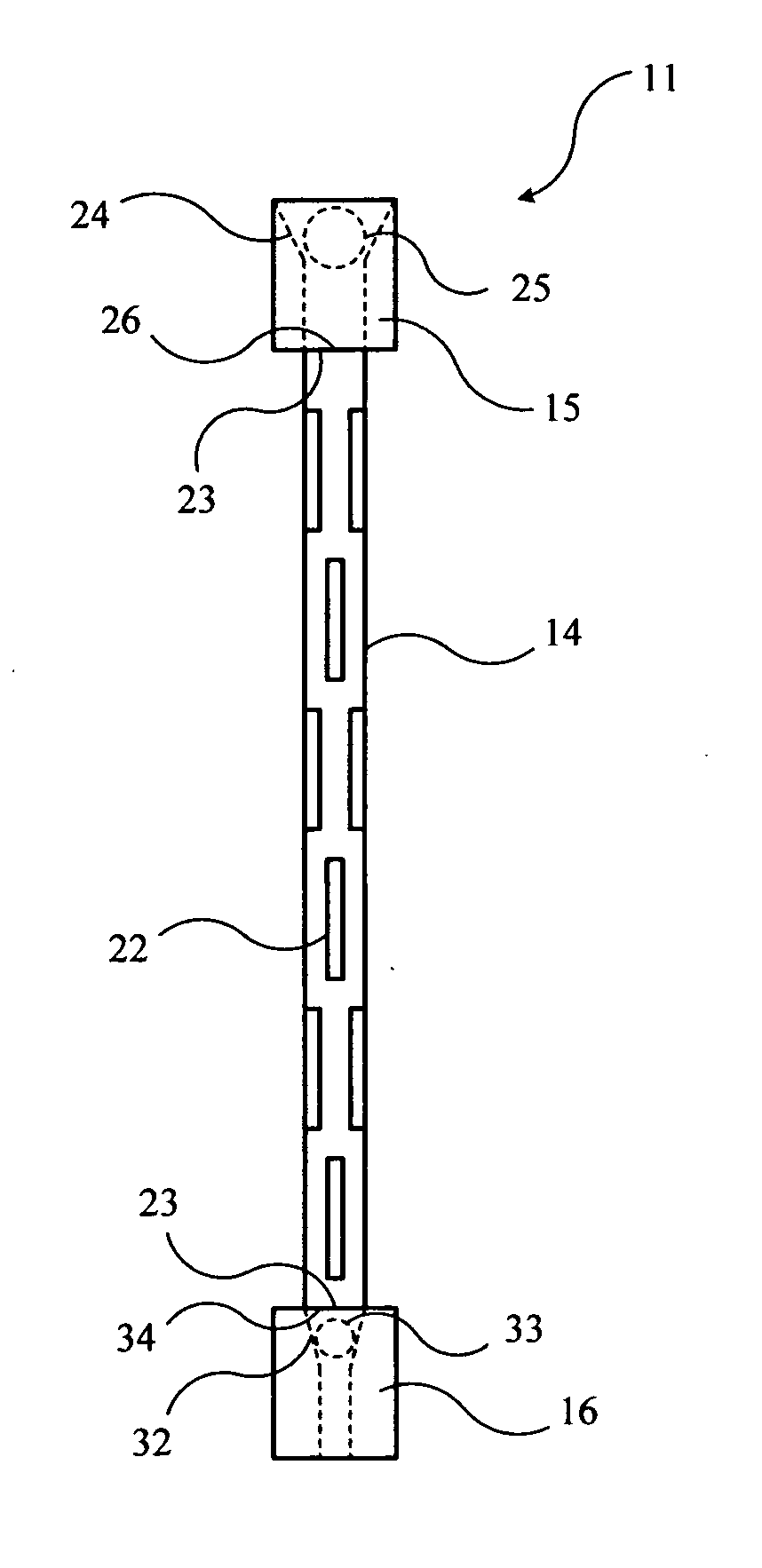
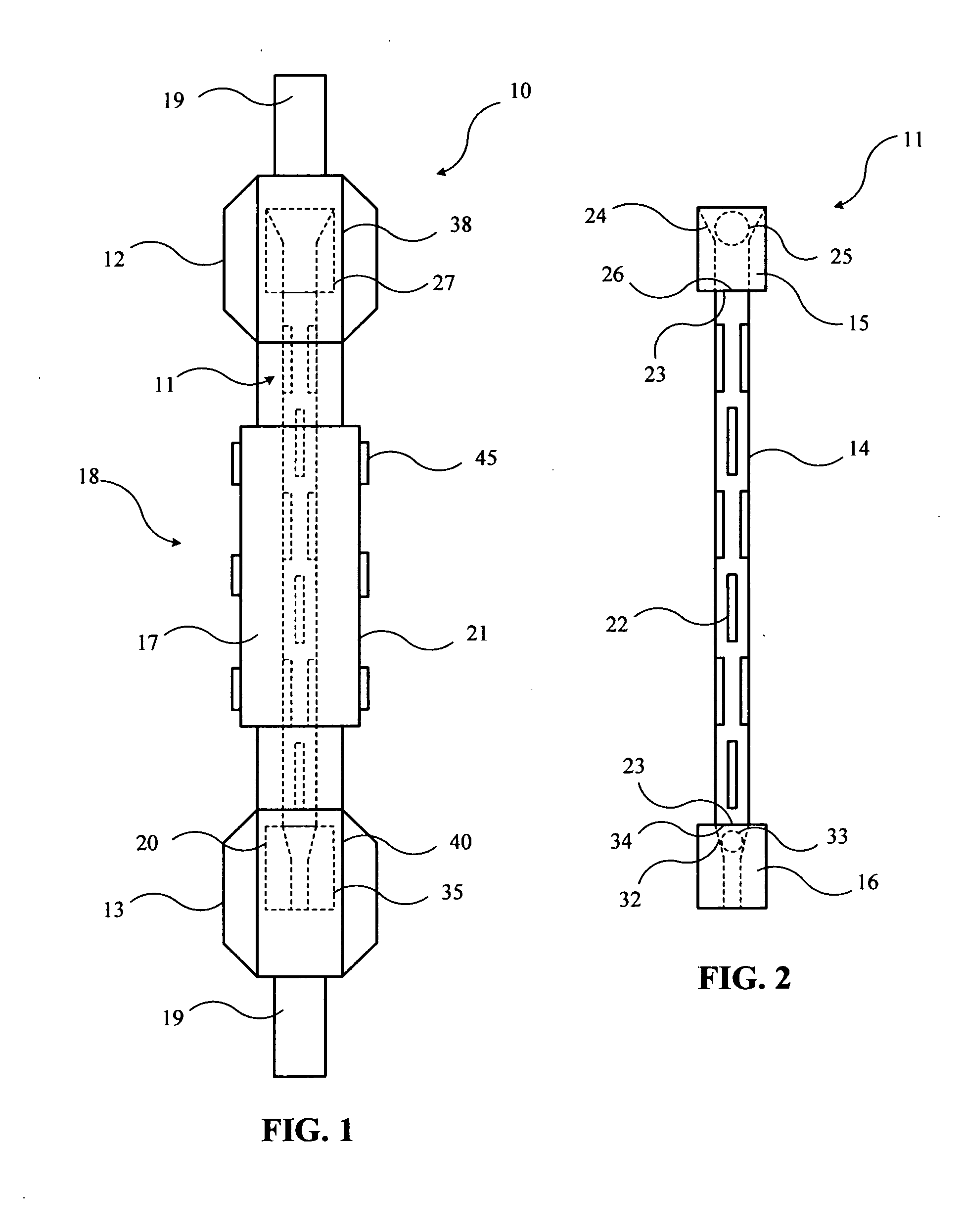
[0031]The invention is an apparatus, a flow isolation tool assembly, and a method for using this flow isolation tool assembly in a well. The invention allows fluid flow through an inner diameter of an assembly of downhole tools in a well, then selectively blocks the fluid flow at a desired location in the assembly of tools, and finally allows re-establishment of fluid flow through the tools again after the desired task is complete. In a preferred embodiment, the invention is used with an abrasive jet perforating tool in wells, but the invention is not limited to this use. The invention could be used in other oilfield related bottomhole tool assemblies in which fluid flow diversion or isolation is desired. Use of this flow isolation tool assembly allows for multiple tasks to be accomplished in one trip down the well.

[0032]FIG. 1 shows a schematic side view (not necessarily to scale) of an embodiment of the flow isolation tool assembly of the invention. FIG. 1 shows a basic embodiment...


PUM


Abstract

An apparatus for isolating fluid flow in a bottomhole tool assembly comprises a generally cylindrically shaped flow tube with a side, a top, and a bottom; an upper ball seat connected to the top of the flow tube; a lower ball seat connected to the bottom of the flow tube; a plurality of openings in the side of the flow tube; a tapered inner diameter in the upper ball seat, acting as a ball valve; a tapered inner diameter in the lower ball seat, acting as a ball valve, smaller than the tapered inner diameter in the upper ball seat; an upper sub attached to the bottomhole tool assembly; a lower sub attached to the bottomhole tool assembly; shear pins connecting the upper ball seat to the upper sub; and a limiting pin in the lower sub below the lower ball assembly.

Description

CROSS-REFERENCES TO RELATED APPLICATIONS[0001]Not ApplicableFEDERALLY SPONSORED RESEARCH OR DEVELOPMENT[0002]Not ApplicableSEQUENCE LISTING, TABLE, OR COMPUTER LISTING[0003]Not ApplicableBACKGROUND OF THE INVENTION[0004]1. Field of the Invention[0005]This invention relates generally to the field of treating wells to stimulate fluid production. More particularly, the invention relates to the field of combining the use of downhole tools with the use of abrasive jet perforating tools in a single trip in a well.[0006]2. Description of the Related Art[0007]Abrasive jet perforating uses fluid slurry pumped under high pressure to perforate tubular goods around a wellbore, where the tubular goods include tubing, casing, and cement. Since sand is the most common abrasive used, this technique is also known as sand jet perforating (SJP). Abrasive jet perforating was originally used to extend a cavity into the surrounding reservoir to stimulate fluid production. It was soon discovered, however,...

Claims


Application Information

Patent Timeline
Patent Type & Authority Applications(United States)
IPC IPC(8): E21B34/06E21B43/114
CPCE21B43/114E21B34/06E21B21/103
Inventor DOTSON, THOMAS L.TUCKER, BARRETT
Owner TD TOOLS
Why Eureka
Try Eureka