Eureka AIR delivers breakthrough ideas for toughest innovation challenges, trusted by R&D personnel around the world.

Flexible connection between a wall and a case of a turbine engine

Active Publication Date: 2014-04-03
RAYTHEON TECH CORP
View PDF27 Cites 0 Cited by
  • Summary
  • Abstract
  • Description
  • Claims
  • Application Information

AI Technical Summary

Benefits of technology

The invention provides a wall assembly for a turbine engine, which includes a wall, mounting brackets, and wall brackets. The mounting brackets have grooves that extend axially into them, and the wall brackets have tongues that fit into the grooves. The wall bracket has a mount that connects to the core case, and the mounting bracket has a groove that connects to the wall bracket. The wall bracket has a base and a mount that connects to the core case. The wall assembly also includes a bypass duct with mounting brackets and wall brackets. The invention provides a more efficient and reliable connection between the wall and the core case, which helps to improve the performance of the turbine engine.

Problems solved by technology

Such rigid connections, however, enable loads to be transferred from the case to the duct wall, which can significantly increase internal stresses within the duct wall.

Method used


Image

  • Flexible connection between a wall and a case of a turbine engine
  • Flexible connection between a wall and a case of a turbine engine
  • Flexible connection between a wall and a case of a turbine engine

Examples


Embodiment Construction

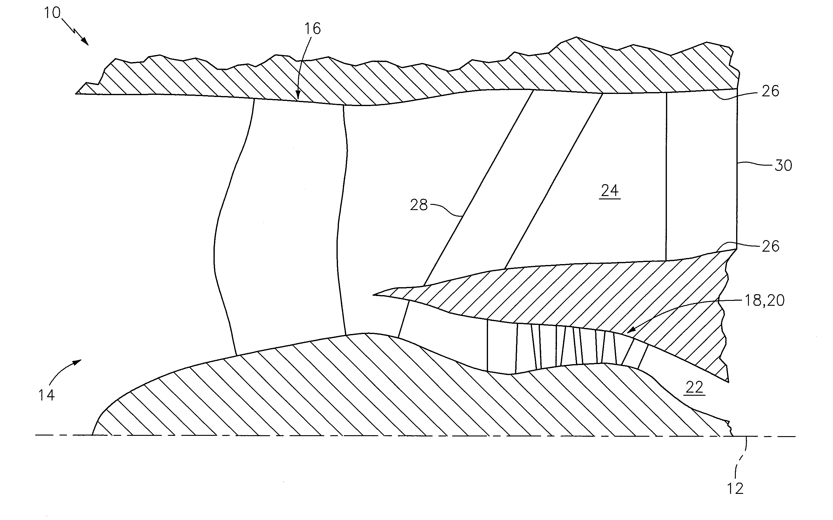
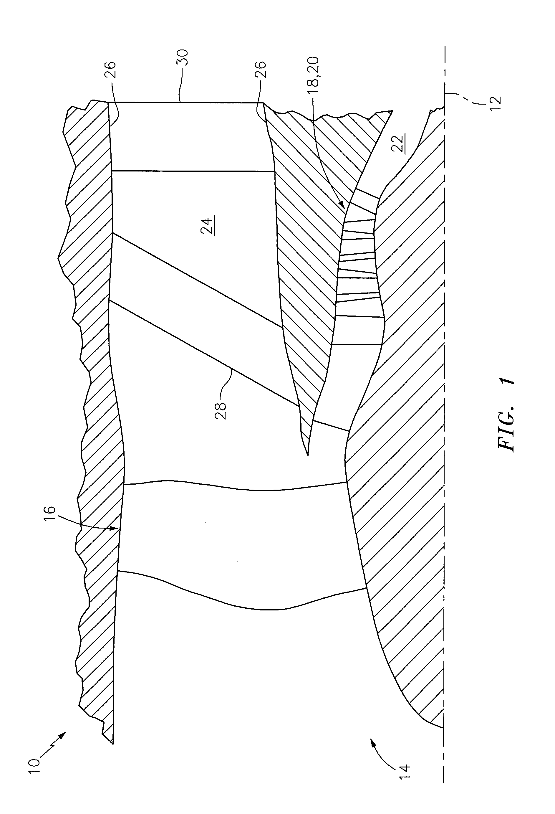
[0028]FIG. 1 is a sectional illustration of a forward portion of a turbine engine 10. The engine 10 extends axially along a centerline 12 between a forward airflow inlet 14 and an aft airflow exhaust. The engine 10 includes a fan section 16 and a turbine engine core 18, which includes a compressor section 20, a combustor section and a turbine section.

[0029]Air enters the engine 10 through the airflow inlet 14, and is directed through the fan section 16 and into an annular core gas path 22 and an annular bypass gas path 24. The air within the core gas path 22 may be referred to as “core air”. The air within the bypass gas path 24 may be referred to as “bypass air” or “cooling air”. The core air is directed through the core 18 and exits the engine 10 through the airflow exhaust. Within the core 18, fuel is injected into and mixed with the core air and ignited to provide engine thrust. The bypass air may be directed through the bypass gas path 24 and out of the engine 10 to provide add...


PUM


Abstract

A wall assembly includes a wall that extends axially along a centerline, and circumferentially at least partially around the centerline. The wall assembly also includes a plurality of mounting brackets arranged circumferentially around the centerline, and a plurality of wall brackets. Each of the mounting brackets includes a groove that extends axially into the respective mounting bracket. Each of the wall brackets includes a tongue and a base. The tongue extends axially from the base into the groove of a respective one of the mounting brackets. The base is connected to the wall.

Description

BACKGROUND OF THE INVENTION[0001]1. Technical Field[0002]This disclosure relates generally to a turbine engine and, more particularly, to a connection between a bypass duct wall and a turbine engine case.[0003]2. Background Information[0004]A turbine engine may include an annular bypass gas path that directs bypass air out of the engine to provide engine thrust. Such a bypass gas path is defined by a bypass duct, which may include an annular inner bypass duct wall arranged adjacent to and downstream of a plurality of exit guide vanes. Opposing axial ends of the duct wall may be rigidly connected to a case that houses a turbine engine core. Such rigid connections, however, enable loads to be transferred from the case to the duct wall, which can significantly increase internal stresses within the duct wall.SUMMARY OF THE DISCLOSURE[0005]According to an aspect of the invention, a wall assembly is provided for a turbine engine. The wall assembly includes a wall, a plurality of mounting ...

Claims


Application Information

Patent Timeline
IPC IPC(8): F02C7/20
CPCF02C7/20F01D9/02F02K3/06F05D2260/941
Inventor SALAMON, KEITH T.TURNER, MATTHEW A.TIRONE, JOHN P.
Owner RAYTHEON TECH CORP
Why Eureka
Eureka Blog
Learn More