System for detecting surrounding conditions of moving body

Active Publication Date: 2014-04-10
PIONEER CORP
View PDF42 Cites 40 Cited by
  • Summary
  • Abstract
  • Description
  • Claims
  • Application Information

AI Technical Summary

Benefits of technology

[0005]The present invention has been developed in order to solve the above-described problem, and its object is to provide a system for detecting surrounding conditions of a m

Problems solved by technology

However, there is a problem; to check contents displayed on the on-vehicle display unit, the drive

Method used


Image

  • System for detecting surrounding conditions of moving body
  • System for detecting surrounding conditions of moving body
  • System for detecting surrounding conditions of moving body

Examples


embodiments

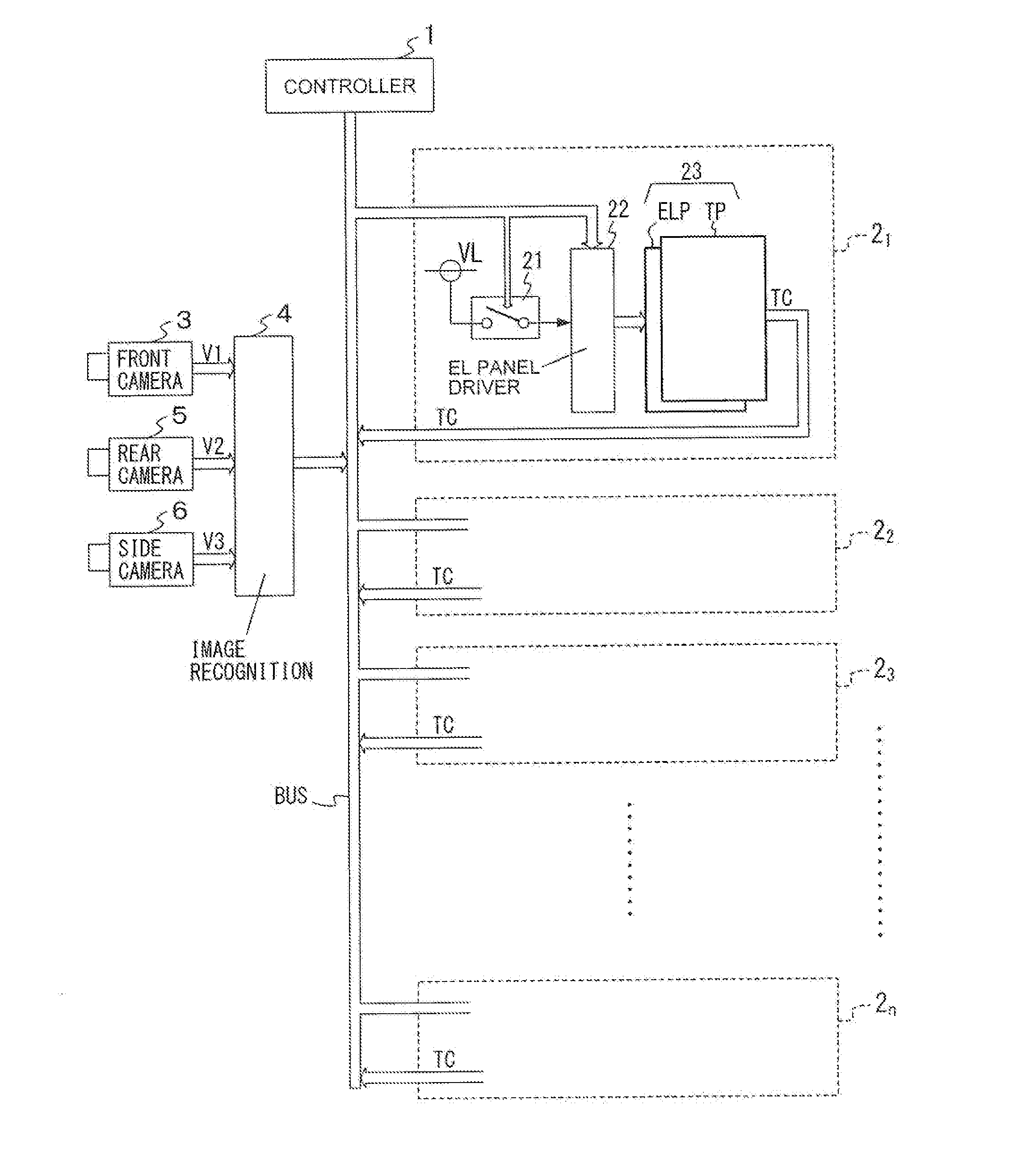
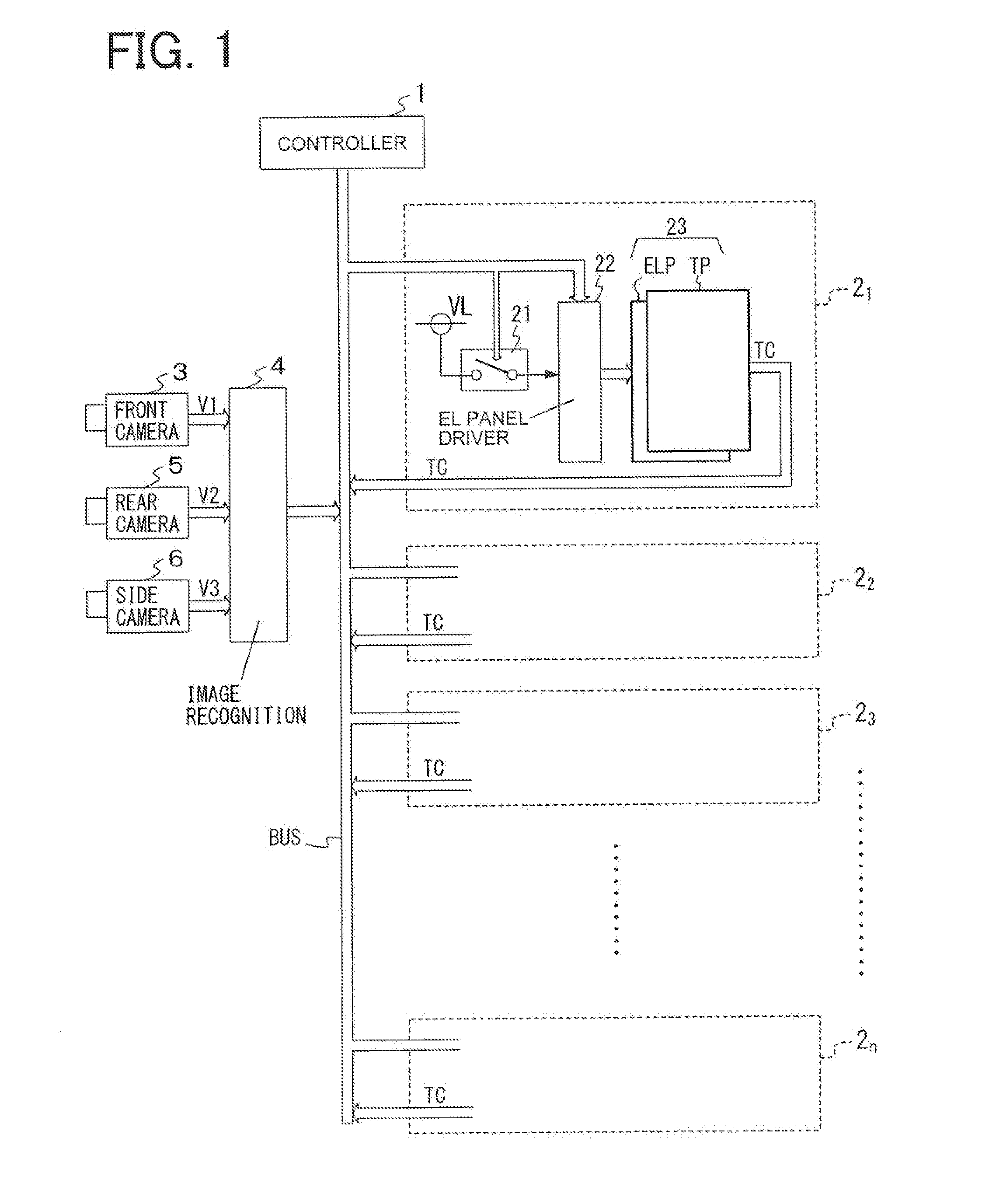
[0022]FIG. 1 is a block diagram of a system configuration when a system for detecting surrounding conditions of a moving body according to the present invention is provided in a vehicle.

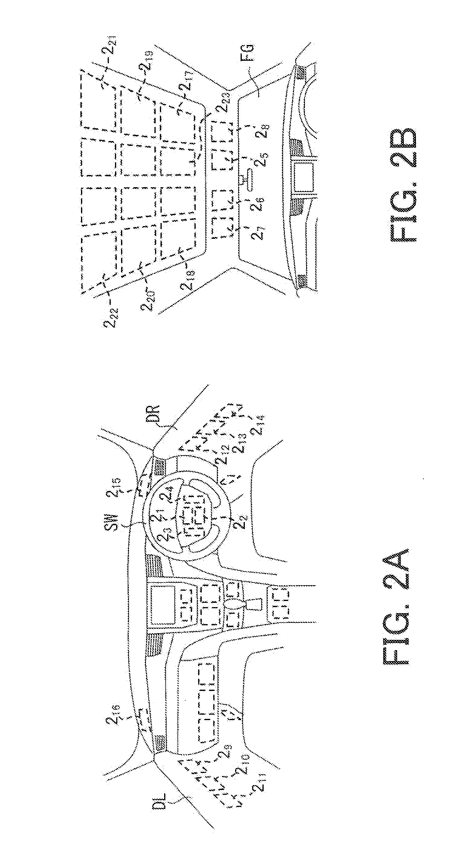
[0023]In FIG. 1, illumination panels 21 to 2n (n represents an integer equal to or more than two), each of which serves as a lighting device or an illumination device, are installed, for example, at a front panel in front of a driver's seat, a steering wheel SW, a console box, doors DL and DR in the vehicle as illustrated by the dashed lines shown in FIG. 2A and on the ceiling in the vehicle illustrated by the dashed lines shown in FIG. 2B, respectively. The illumination panels 21 to 2n are coupled to a controller 1 via a control bus BUS, respectively. A front camera 3, a rear camera 5, and a side camera 6 are also coupled to the controller 1 via the control bus BUS.

[0024]The illumination panels 21 to 2n have the same internal configuration.

[0025]When the controller 1 sends a lighting or a blinking c...


PUM


Abstract

This system for detecting the surrounding: conditions of a moving body forcibly changes the state of at least one of a plurality of lighting devices (change from an unlit stats to a lighting state or a blinking state, change in the emission color, or change in the luminance) installed inside the moving body if an object to which attention must be paid during traveling of the moving body is detected in the surroundings of the moving body.

Description


Claims


Application Information

Patent Timeline
Owner PIONEER CORP
Why Eureka
Try Eureka