Display device

a technology of a display device and a display plate, which is applied in the direction of identification means, lighting and heating apparatus, instruments, etc., can solve the problems of easy peeling and damage of the outside of the light shielding layer, and achieve the effect of preventing the peeling of the outer layer

Active Publication Date: 2014-05-15
AU OPTRONICS CORP
View PDF1 Cites 13 Cited by
  • Summary
  • Abstract
  • Description
  • Claims
  • Application Information

AI Technical Summary

Benefits of technology

[0007]As mentioned in the above, the invention disposes the fading pattern at at least one side of opposite sides of the light shielding layer and the fading pattern comprises at least two light transmissible areas with different transmittances. Through the variation of different transmittances, the co

Problems solved by technology

Furthermore, the display device 1 is always cut and grinded during manufacture su

Method used


Image

  • Display device
  • Display device
  • Display device

Examples


Embodiment Construction

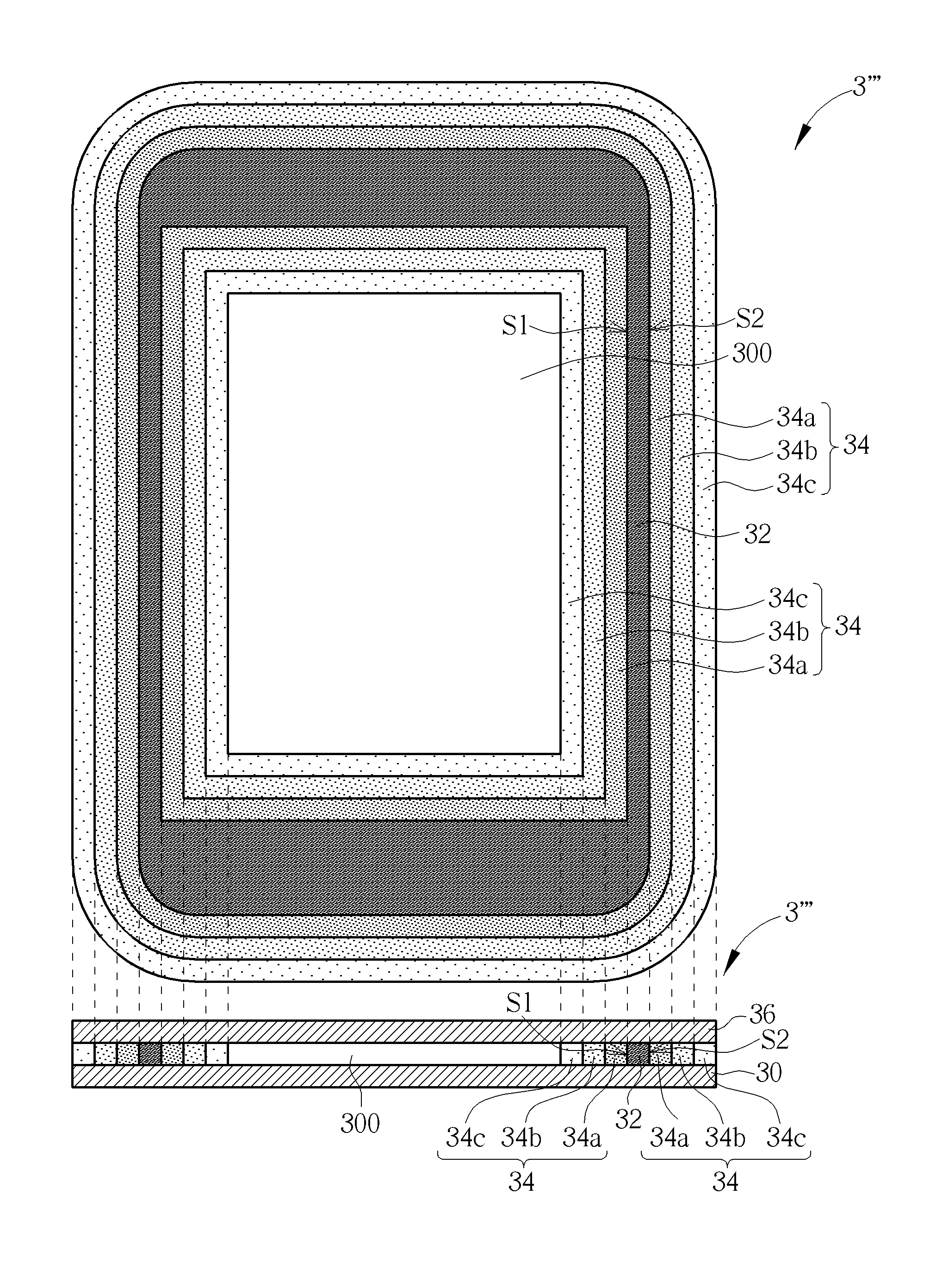
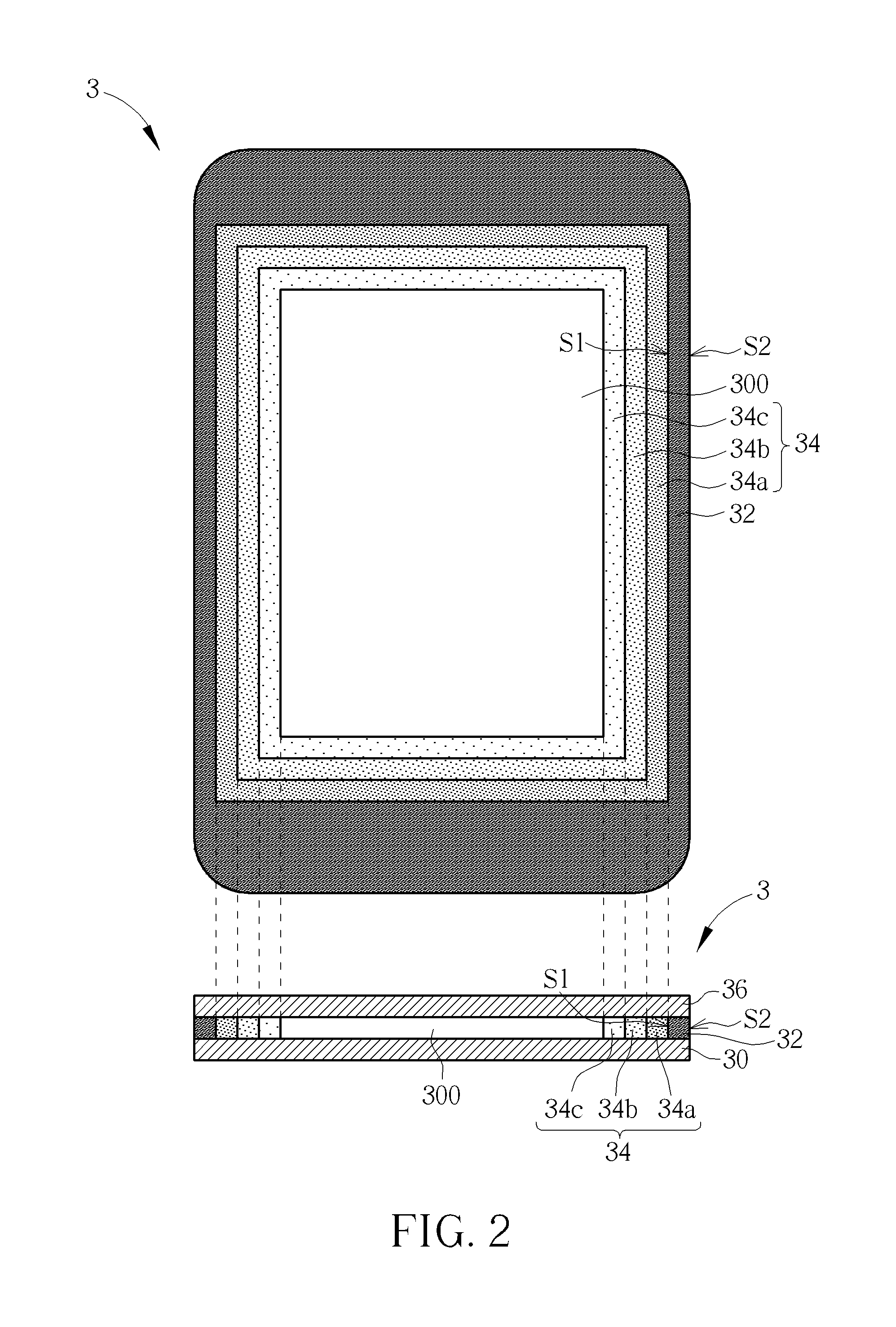
[0019]Referring to FIG. 2, FIG. 2 is a schematic front and cross-sectional view illustrating a display device 3 according to an embodiment of the invention. As shown in FIG. 2, the display device 3 comprises a substrate 30, a light shielding layer 32, a fading pattern 34 and a display module 36. The light shielding layer 32 is disposed on the substrate 30 and has a first side S1 and a second side S2, wherein the first side S1 is opposite to the second side S2. In general, the substrate 30 has a display area 300 and the light shielding layer 32 is disposed on a periphery of the substrate 30, surrounding the display area 300, for example. Therefore, the first side S1 represents the inside of the light shielding layer 32 relative to the display area 300 and does not overlap the display area 300, and the second side S2 represents the outside of the light shielding layer 32 relative to the display area 300. In other words, the first side S1 of the light shielding layer 32 is close to the...


PUM


Abstract

A display device includes a substrate, a light shielding layer, at least one fading pattern and a display module. The display module is disposed on the substrate and has a display area. The light shielding layer is disposed on a periphery of the substrate and has a first side and a second side, wherein the first side is opposite to the second side. The at least one fading pattern is disposed on the substrate, is adjacent to at least one side of the first side and the second side of the light shielding layer, and does not overlap the display area of the display module. Each fading pattern includes N light transmissible areas, the N light transmissible areas are adjacent to each other, and transmittances of the N light transmissible areas are different from each other, wherein N is a positive integer larger than one.

Description

BACKGROUND OF THE INVENTION[0001]1. Field of the Invention[0002]The invention relates to a display device and, more particularly, to a display device having fading pattern(s) adjacent to at least one side of two opposite sides of a light shielding layer.[0003]2. Description of the Prior Art[0004]Referring to FIG. 1, FIG. 1 is a schematic front view illustrating a display device 1 of the prior art. As shown in FIG. 1, to prevent light from leaking out from a periphery of the display device 1 and to hide some components disposed at a frame of the display device 1, a light shielding layer 12 (i.e. well-known black matrix, BM) is formed on the periphery of a display area 10 over a glass substrate of the display device 1. However, when the display device 1 is switched off, a boundary between the light shielding layer 12 and the display area 10 is obvious due to color contrast between the light shielding layer 12 and the display area 10. Accordingly, the display device 1 cannot show a ful...

Claims


Application Information

Patent Timeline
IPC IPC(8): F21V11/08
CPCF21V11/08G09F9/30G02F1/133512G02F2203/30G02F1/133388G02F1/1335G09F13/00
Inventor SUNG, WEN-CHINGCHEN, CHIEN-WEILIN, CHENG-HSINGTANG, YU-YINGKUO, WEI-HUNGCHOU, SHIH-PO
Owner AU OPTRONICS CORP
Why Eureka
Try Eureka