Steering system

Inactive Publication Date: 2014-05-22
JTEKT CORP
View PDF6 Cites 5 Cited by
  • Summary
  • Abstract
  • Description
  • Claims
  • Application Information

AI Technical Summary

Benefits of technology

The invention relates to a steering system for vehicles. It includes a steered shaft that moves back and forth, a housing for containing the shaft, and a joint that connects the shaft to a steered wheel. An impact absorbing member is placed between the housing and the joint to soak up any impact that might occur when the two parts make contact with each other. The impact absorbing member has a layer of elastic material and a layer of elastic material with a higher elastic modulus. When the parts make contact with each other, the compression allowance between the two layers is zero, which means that the impact absorbing member allows for no compression. This results in a safer and more stable connection between the steering system and the vehicle.

Problems solved by technology

In the steering system that includes the above-described steered mechanism, when the rack end comes into contact with a rack housing that accommodates the rack shaft, the movement of the rack shaft is mechanically restricted.
Furthermore, if the reverse input is greater than the steering input caused by a driver's steering operation, there is a possibility that the rack end may be moved to collide with the rack housing due to the reverse input and a strong impact may act on a steering system.
Therefore, when the driver steers the steering wheel until the steering angle becomes a steering angle close to the allowable steering angle, the driver feels a sense of discomfort due to elasticity caused by the deformation of the impact absorbing member.
That is, even a slight change in the steering input causes a change in the angle of the steered wheels.
Therefore, the drivability may be deteriorated.

Method used


Image

  • Steering system
  • Steering system
  • Steering system

Examples


Embodiment Construction

[0021]Hereinafter, embodiments of the invention will be described with reference to the accompanying drawings.

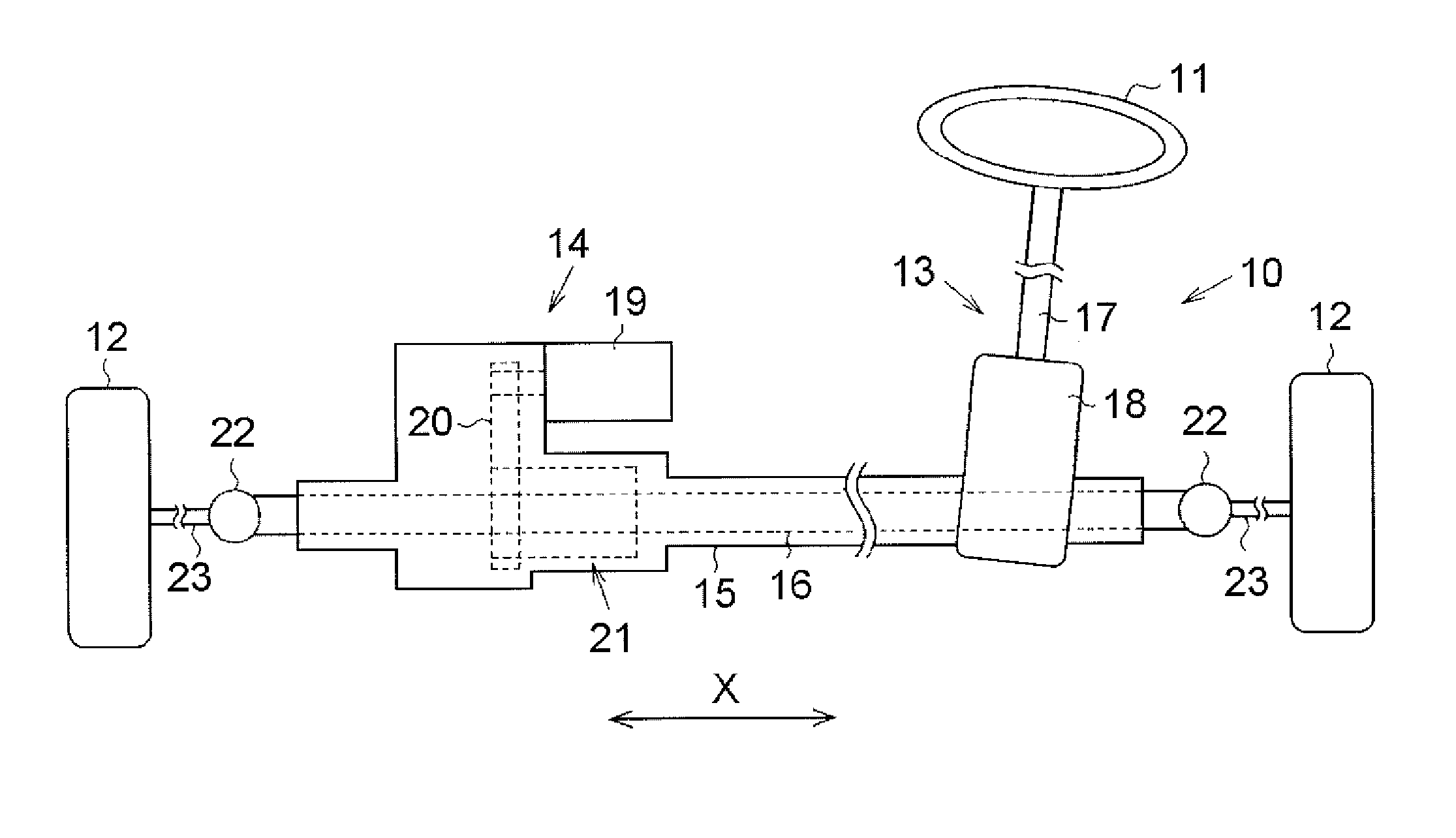
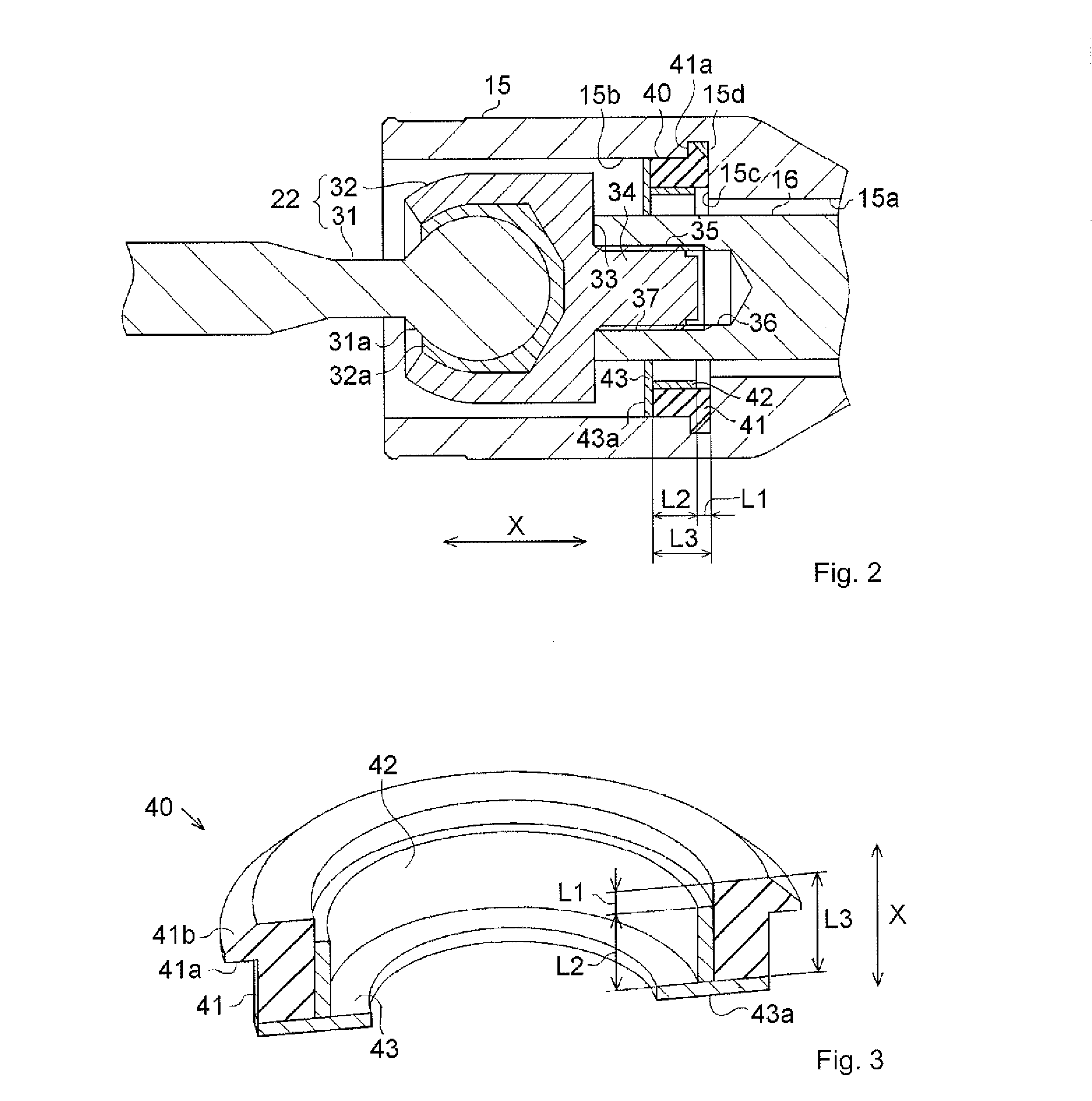
[0022]An embodiment of the invention, in which a steering system according to the invention is implemented as an electric power steering system, will be described with reference to the accompanying drawings. As illustrated in FIG. 1, an electric power steering system 10 (hereinafter, referred to as “steering system 10” where appropriate) includes a steered mechanism 13 that transmits the rotation of a steering wheel 11 to steered wheels 12, and an assist device 14 that assists the steering of the steering wheel 11. In addition, the steering system 10 includes a rack housing 15, which is an example of a housing and which is extended in the lateral direction of a vehicle, and a rack shaft 16, which is an example of a steered shaft, which is arranged inside the rack housing 15, and which is extended in the lateral direction of the vehicle. Hereinafter, the lateral direction of ...


PUM


Abstract

A steering system includes a rack shaft, a rack housing, a rack end, and an impact absorbing member that is provided between a restriction face formed within the rack housing and an end face of the rack end, and that absorbs an impact generated when the restriction face and the end face come into contact with each other. The impact absorbing member includes an elastic portion, and a restriction portion having an elastic modulus higher than that of the elastic portion and having a length in the axial direction, which is shorter than that of the elastic portion. A compression allowance, which is a difference in length in the axial direction between the elastic portion and the restriction portion, is brought to zero when the restriction face and the end face come into contact with each other via the impact absorbing member due to a steering input.

Description

INCORPORATION BY REFERENCE / RELATED APPLICATION[0001]This application claims priority to Japanese Patent Application No. 2012-252332 filed on Nov. 16, 2012, the disclosure of which, including the specification, drawings and abstract, is incorporated herein by reference in its entirety.BACKGROUND OF THE INVENTION[0002]1. Field of the Invention[0003]The invention relates to a steering system.[0004]2. Discussion of Background[0005]In a conventional vehicle steering system, the rotation of a steering shaft caused by steering of a steering wheel is transmitted to a steered mechanism such as a rack-and-pinion mechanism. Thus, the angle of steered wheels is changed. A rack end is provided at each shaft end portion of a rack shaft that constitutes the above-described rack-and-pinion mechanism. The rack end connects a tie rod to the rack shaft such that the tie rod is pivotable relative to the rack shaft. When the steering wheel is steered, a steering input that acts on the rack shaft is tran...

Claims


Application Information

Patent Timeline
IPC IPC(8): B62D1/16
CPCB62D1/16B62D3/12Y10T403/32811
Inventor OHASHI, TATSUYA
Owner JTEKT CORP
Why Eureka
Try Eureka