Image coding method and image decoding method
a coding method and image technology, applied in the field of image coding methods, can solve the problems of deteriorating coding efficiency and coding efficiency, and achieve the effect of improving coding efficiency
- Summary
- Abstract
- Description
- Claims
- Application Information
AI Technical Summary
Benefits of technology
Problems solved by technology
Method used
Image

Examples
first embodiment
[0143]First, the description is given for a summary of an image coding device according to the first embodiment of the present invention. The image coding device according to the first embodiment divides a picture into slices and permits the slices to refer to each other. The image coding device according to the first embodiment adopts, at the beginning of each slice, a symbol occurrence probability table of a neighboring macroblock of the first macroblock in the slice. Thereby, the image coding device according to the first embodiment can use the symbol occurrence probability table appropriate for a target image (macroblock). Therefore, it is possible to improve coding efficiency.
[0144]This is the summary of the image coding device according to the first embodiment.
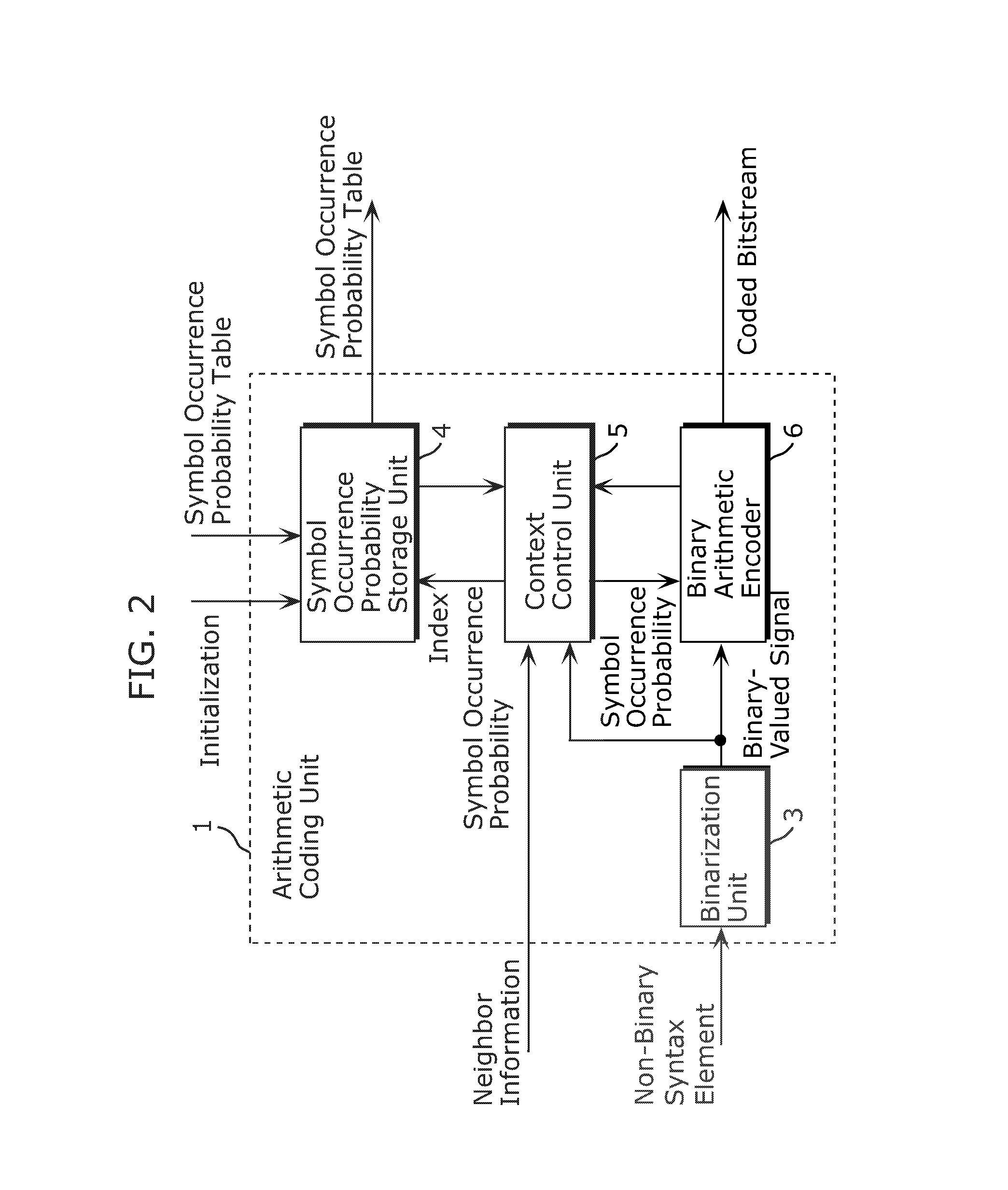
[0145]The following describes a structure of the image coding device according to the first embodiment. FIG. 1 is a block diagram showing the structure of the image coding device according to the first embodiment. The im...
second embodiment
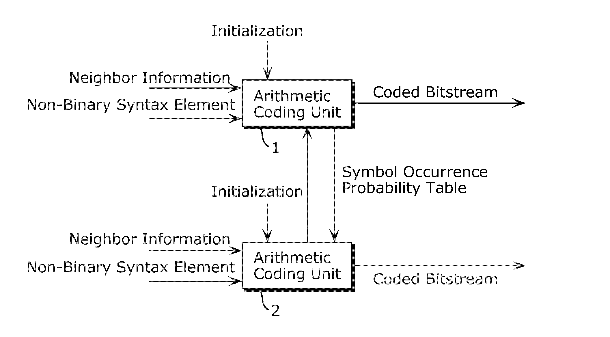
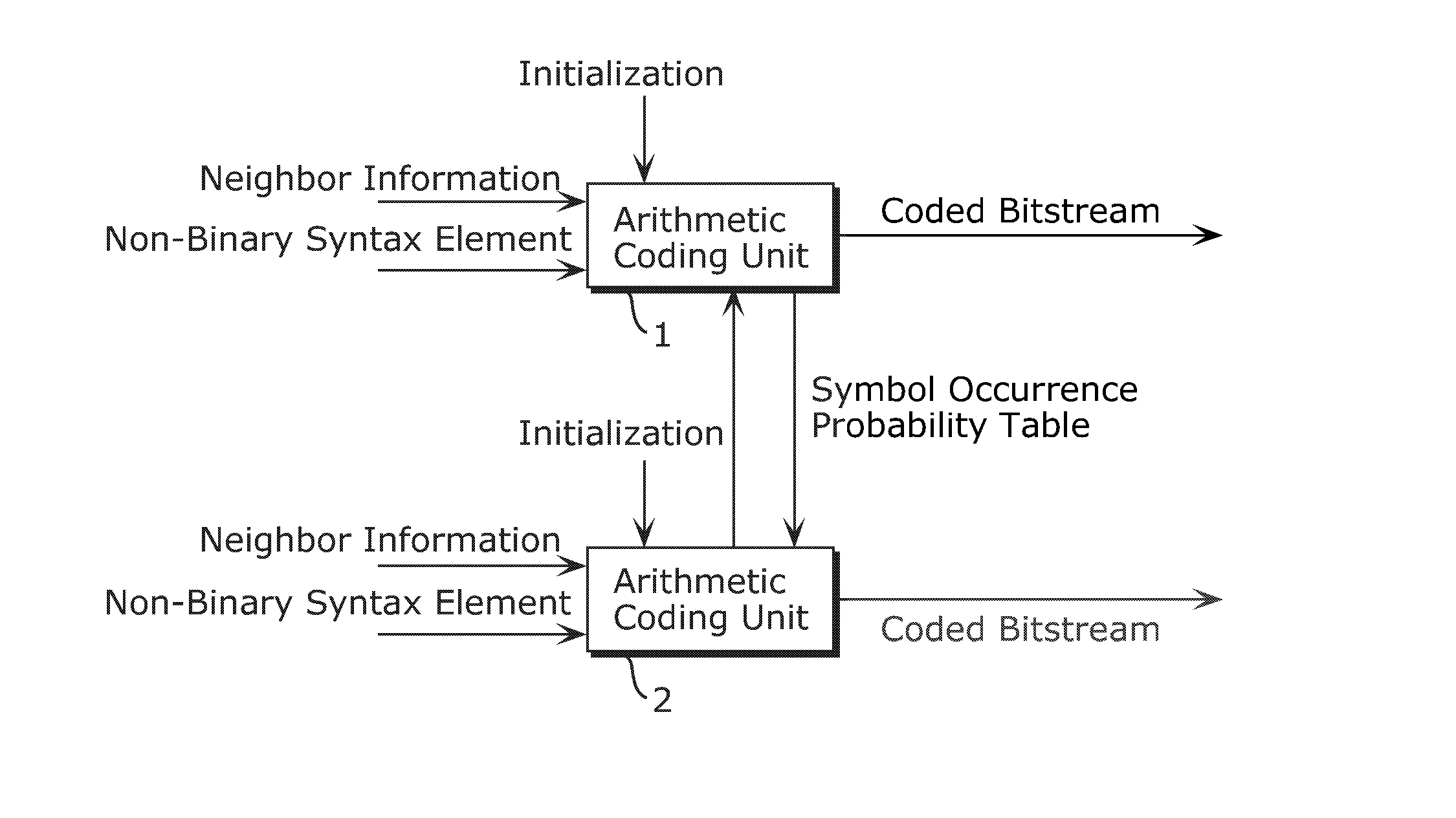
[0170]Here, the description is given for a summary of an image coding device according to the second embodiment of the present invention. The image coding device according to the second embodiment differs from the image coding device according to the first embodiment in that a position of an image for which a symbol occurrence probability table is outputted is spatially closer to a position of an image which is coded based on the outputted symbol occurrence probability table. Thereby, the image coding device according to the second embodiment can further improve coding efficiency.
[0171]This is the summary of the image coding device according to the second embodiment.
[0172]Since the structure of the image coding device according to the second embodiment is the same as the structure of the image coding device according to the first embodiment, it will be not explained again.
[0173]The following describes processing performed by the image coding device according to the second embodiment...
third embodiment
[0185]Here, the description is given for a summary of an image coding device according to the third embodiment of the present invention. The image coding device according to the third embodiment differs from the image coding devices according to the first and second embodiments in that a symbol occurrence probability table outputted for a macroblock that is spatially closer to a target macroblock is used not only in coding the first macroblock in each slice, but in coding any macroblocks. As a result, it is possible to further improve coding efficiency.
[0186]This is the summary of the image coding device according to the third embodiment.
[0187]The following describes a structure of the image coding device according to the third embodiment. Since the structure of the image coding device according to the third embodiment is the same as the structure of the image coding device according to the first embodiment shown in FIG. 1, it will be not explained again. FIG. 11 is a block diagram ...
PUM
 Abstract
Description
Claims
Application Information
 - R&D
- Intellectual Property
- Life Sciences
- Materials
- Tech Scout
- Unparalleled Data Quality
- Higher Quality Content
- 60% Fewer Hallucinations
Browse by: Latest US Patents, China's latest patents, Technical Efficacy Thesaurus, Application Domain, Technology Topic, Popular Technical Reports.
© 2025 PatSnap. All rights reserved.Legal|Privacy policy|Modern Slavery Act Transparency Statement|Sitemap|About US| Contact US: help@patsnap.com